
Card installing device

A technology for installing devices and cards, which is applied in the connection/disconnection of connection devices, instruments, computer parts, etc., and can solve problems such as damage to card readers.

Inactive Publication Date: 2013-09-11
HANNSTAR DISPLAY CORPORATION
View PDF3 Cites 2 Cited by
  • Summary
  • Abstract
  • Description
  • Claims
  • Application Information

AI Technical Summary

Problems solved by technology

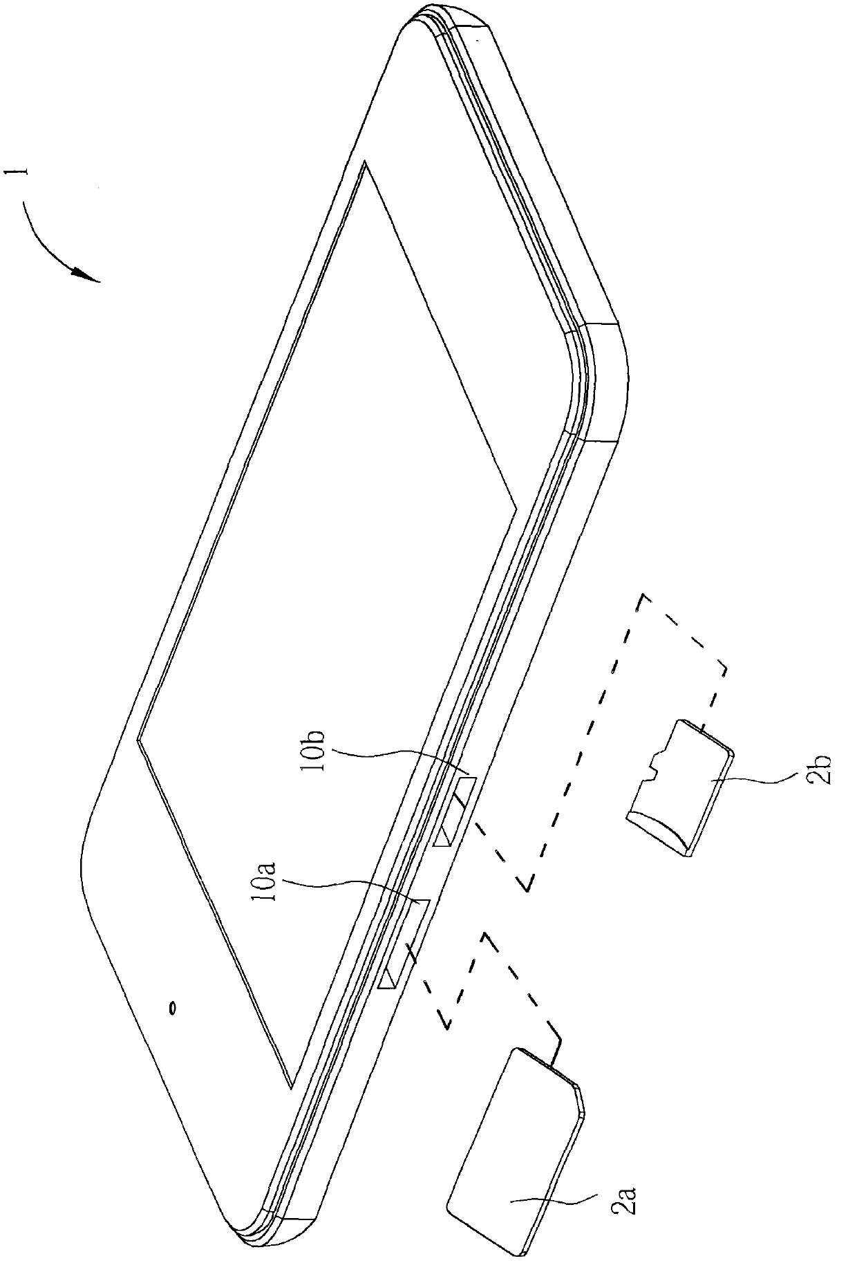
Due to the small size of the cards 2a, 2b, it will cause considerable trouble for the user to insert the cards 2a, 2b into the corresponding card slots 10a, 10b with bare hands.
If the card 2a, 2b is not aligned with the card slot 10a, 10b or the user applies improper force, it will cause damage to the card 2a, 2b and / or the card reader in the card slot 10a, 10b

Method used


Image

  • Card installing device
  • Card installing device
  • Card installing device

Examples


Embodiment Construction

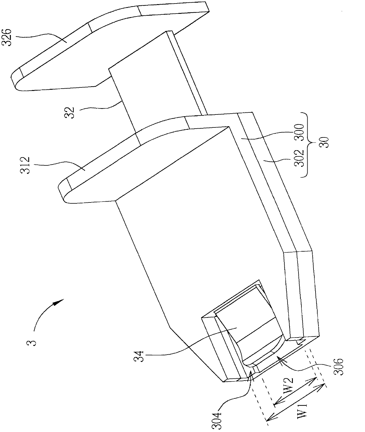
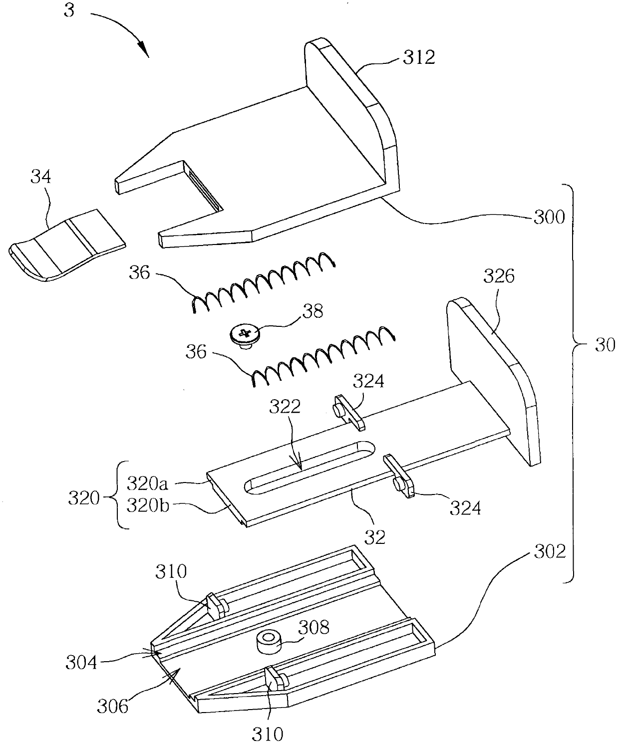
[0057] Please refer to Figure 2 to Figure 6 , figure 2 It is an assembly diagram of the card installation device 3 according to an embodiment of the present invention, image 3 yes figure 2 An exploded view of the card mounting device 3 in, Figure 4 yes image 3 A partial assembly diagram of the card mounting device 3 in, Figure 5 The first card 4a and the second card 4b are installed on the figure 2 A schematic diagram of the housing 30 of the card installation device 3, Figure 6 yes Figure 5 A schematic diagram of pushing the first card 4 a and the second card 4 b out of the housing 30 by the pusher 32 in the figure.

[0058] Such as Figure 2 to Figure 4 As shown, the card installation device 3 includes a housing 30 , a pusher 32 , an elastic piece 34 , two elastic pieces 36 and a fixing piece 38 . In this embodiment, the casing 30 includes an upper casing 300 and a lower casing 302 , and the upper casing 300 and the lower casing 302 are detachably combined...


PUM


Abstract

The invention discloses a card installing device which comprises a shell body and a pushing piece. The shell body is provided with a containing groove, and the containing groove is used for containing a card. The pushing end of the pushing piece is movably arranged in the shell body, the pushing end is used for pushing the card when the card is contained in the containing groove so that the card is pushed into a card inserting groove of an electronic device. Therefore, the card and / or a card reader in the card inserting groove can be prevented from damage caused when the card is not aligned with the card inserting groove or when a user applies force improperly.

Description

technical field [0001] The invention relates to a card installation device, in particular to a card installation device which can assist a user to install a small card in a card slot of an electronic device. Background technique [0002] Nowadays, various card slots are provided around the casing of electronic devices for inserting corresponding cards, such as Subscriber Identity Module card (Subscriber Identity Module card, SIM card), Micro Secure Digital card (Micro Secure Digital card, Micro SD card), Mini Secure Digital card (Mini Secure Digital card, Mini SD card), Multi Media Card (Multi Media Card, MMC), etc. Please refer to figure 1 , figure 1 It is a schematic diagram of an electronic device 1 and cards 2a, 2b of different sizes in the prior art. Such as figure 1 As shown, the housing side of the electronic device 1 is provided with card slots 10a, 10b for inserting cards 2a, 2b of different sizes. For example, the card 2a can be a SIM card, and the card 2b can...

Claims


Application Information

Patent Timeline
IPC IPC(8): H01R43/26
CPCG06K13/0806Y10T29/53257
Inventor 江长恩
Owner HANNSTAR DISPLAY CORPORATION
Learn More