
Interface switching circuit and device

A technology of interface conversion and circuit, which is applied in the field of interface conversion circuit and device, and can solve the problems of occupying extra I/O ports and complicated program coding

Active Publication Date: 2013-09-11
SHENZHEN HONGDIAN TECH CORP
View PDF3 Cites 13 Cited by
  • Summary
  • Abstract
  • Description
  • Claims
  • Application Information

AI Technical Summary

Problems solved by technology

[0006] The purpose of the present invention is to provide an interface conversion circuit, which aims to solve the problem of complex program coding and the need to occupy additional I / O ports in the prior art

Method used


Image

  • Interface switching circuit and device
  • Interface switching circuit and device

Examples


Embodiment Construction

[0014] In order to make the object, technical solution and advantages of the present invention clearer, the present invention will be further described in detail below in conjunction with the accompanying drawings and embodiments. It should be understood that the specific embodiments described here are only used to explain the present invention, not to limit the present invention.

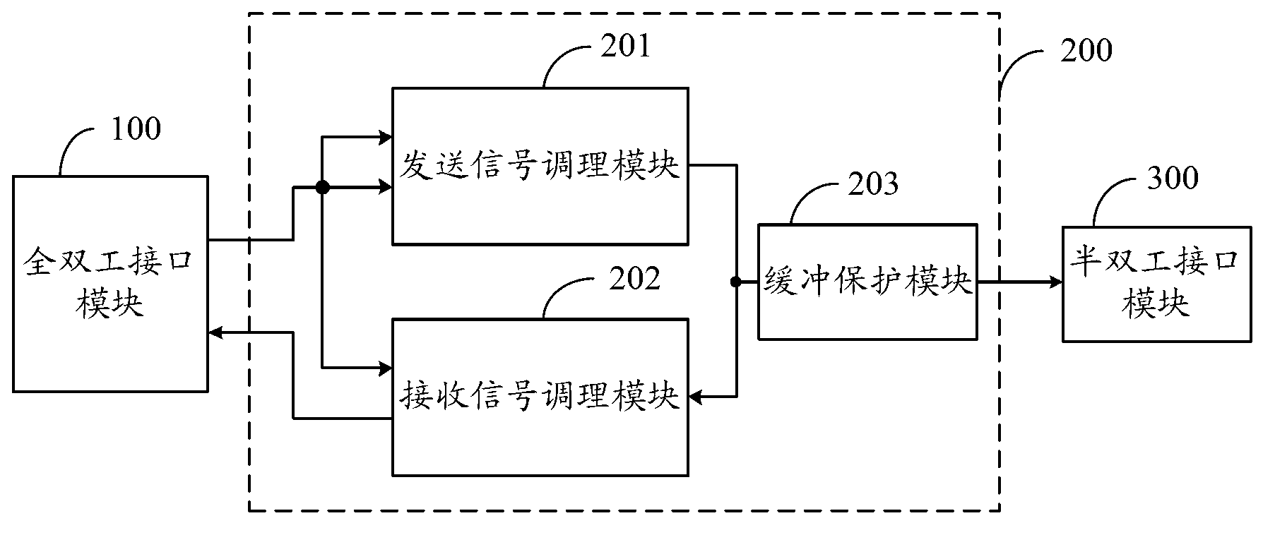
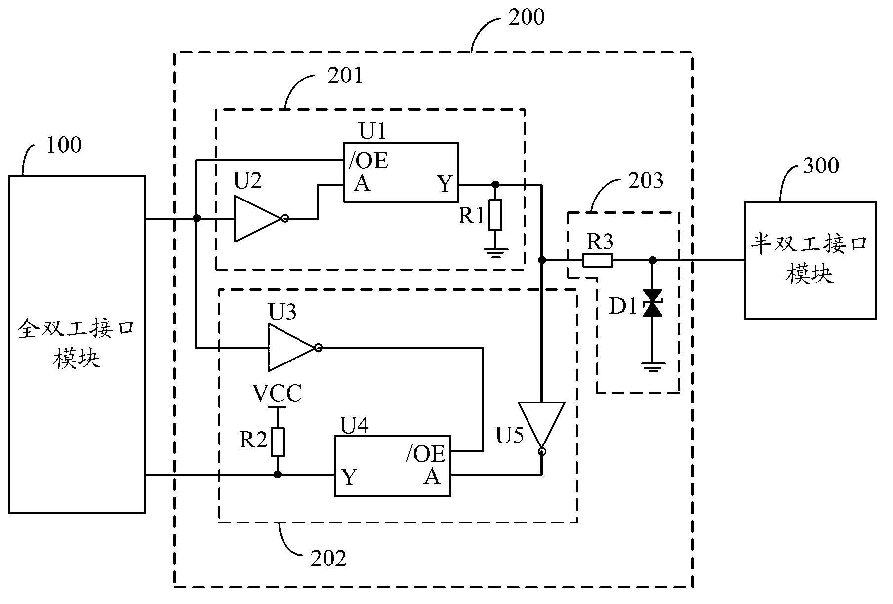
[0015] The embodiment of the present invention realizes the automatic switching function between the state of the sending signal and the state of the receiving signal by adopting an interface conversion circuit including a sending signal conditioning module and a receiving signal conditioning module, and completes the conversion between a full-duplex interface and a half-duplex interface. The circuit can be widely used in interface conversion between a full-duplex interface device and a half-duplex interface device with opposite data levels, and solves the problem in the prior art that the program c...


PUM


Abstract

The invention belongs to the field of signal interfaces, and particularly relates to an interface switching circuit and a device. With the adoption of the interface switching circuit comprising a signal sending conditioning module and a signal receiving conditioning module, the signal sending conditioning module switches on and outputs a second high level signal or cuts off and outputs a low level signal according to a level signal output by a sending end of a full duplex interface module, and the signal receiving conditioning module cuts off and outputs a first high level signal or switches on and outputs the first high level signal or the low level signal opposite to a signal level output by a receiving-sending end of a half duplex interface module according to the level signal output by the full duplex interface module, so that the whole interface switching circuit achieves a function of automatically switching between a signal sending state and a signal receiving state, accomplishes switching between a full duplex interface and a half duplex interface, and has the advantages of program coding simplification and I / O (Input / Output) port saving.

Description

technical field [0001] The invention belongs to the field of signal interfaces, in particular to an interface conversion circuit and device. Background technique [0002] At present, the I / O (Input / Output, input / output) ports of many MCUs (Micro Control Unit, micro control unit) mostly use full-duplex mode to transmit signals, but in many data acquisition equipment and smart sensor communication devices, they use half-duplex mode. Moreover, the high-level signal voltage of these full-duplex interfaces is different from that of most half-duplex interfaces, and cannot directly transmit signals. In order to solve the inconvenience caused by different interfaces, people generally stagger the process of sending and receiving signals by writing programs, and cooperate with external devices to convert high-level voltages to realize full-duplex interfaces and half-duplex interfaces. compatible. [0003] However, the method of writing programs will make the program coding more com...

Claims


Application Information

Patent Timeline
Patent Type & Authority Applications(China)
IPC IPC(8): G06F13/38
Inventor 李俊明
Owner SHENZHEN HONGDIAN TECH CORP
Learn More