A device for automatically switching bus voltage in railway traction station

A technology of automatic switching and bus voltage, applied in the direction of circuit devices, electrical components, emergency power supply arrangements, etc., can solve the problems of switching misoperation, secondary circuit voltage loss, non-maintenance, etc., achieve good stability and reliability, and avoid switching The effect of malfunction and convenient operation and maintenance

Active Publication Date: 2021-07-06
NR ELECTRIC CO LTD +1
View PDF7 Cites 0 Cited by
  • Summary
  • Abstract
  • Description
  • Claims
  • Application Information

AI Technical Summary

Problems solved by technology

However, this scheme relies on not maintaining the contacts X0 and X1 to realize automatic switching. When the voltage loss relay fails or the auxiliary power supply disappears, the contacts X0 and X1 will return to the initial state, and the switching circuit will switch the output voltage to PT-B. If PT- B is in the troubleshooting state, which will cause the loss of pressure in the secondary circuit and affect the safe operation of the equipment
In addition, this solution cannot realize the active and standby flexible switching function of PT-A and PT-B, which brings inconvenience to operation and maintenance
[0005] The Chinese patent No. 200620166601.0 discloses a substation self-switching device, which can realize the unattended operation of the substation. It adopts an ordinary intermediate relay (not holding), but the starting circuit is a self-holding circuit. In the auxiliary power supply In the case of disappearance or failure of the relay itself, it will cause switching malfunction, which will bring inconvenience to operation and maintenance

Method used


Image

  • A device for automatically switching bus voltage in railway traction station
  • A device for automatically switching bus voltage in railway traction station
  • A device for automatically switching bus voltage in railway traction station

Examples


Embodiment Construction

[0023] The technical scheme of the present invention will be described in further detail below in conjunction with the accompanying drawings and specific embodiments, so that those skilled in the art can better understand the present invention and implement it, but the examples given are not intended to limit the present invention.

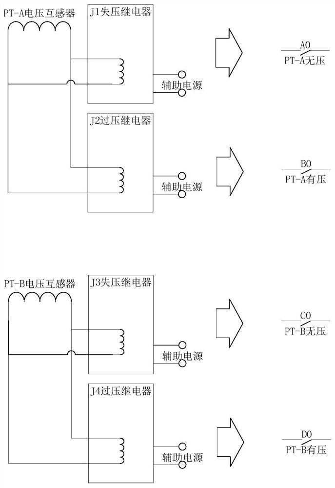
[0024] Such as Figure 3-5 As shown, the traction substation of the electrified railway adopts the method of dual redundant hot standby, and two voltage transformers (set as voltage transformer PT-A and voltage transformer PT-B are set on the low-voltage 27.5kV bus ), a device for automatically switching the bus voltage in a railway traction station, comprising a voltage loss relay J1 and an overvoltage relay J2 connected in parallel at the output end of the voltage transformer PT-A, and a loss relay J2 respectively connected in parallel at the output end of the voltage transformer PT-B. Voltage relay J3 and overvoltage relay J4.

[0025] Wherein...


PUM


Abstract

The invention discloses a device for automatically switching bus voltage in a railway traction station, which includes a voltage loss relay J1, an overvoltage relay J2, a voltage loss relay J3 and an overvoltage relay J4: the output pins of J1 include normally open contacts A0 and J2 The output pins include the normally open contact B0, the normally open contact A0 is connected to the reset pin of the holding relay KJ1 and the normally open contact B0 is connected to the start pin of KJ1, and the output pins of KJ1 include the normally open contact E0 and the normally closed contact E1; the output pin of J3 includes the normally open contact C0, the output pin of J4 includes the normally open contact D0, C0 is connected to the reset pin of the holding relay KJ2 and D0 is connected to the start pin of KJ2, and the output pin of KJ2 includes Normally open contact F0 and normally closed contact F1; E0 and F1 are connected in series, and then connected in parallel with F0, as the main use of PT-B; after F0 and E1 are connected in series, then connected in parallel with E0, as the main use of PT-A; PT‑A main use and PT‑B main use are switched and voltage output through transfer switches respectively. It can effectively avoid switching misoperation.

Description

technical field [0001] The invention relates to a device for automatically switching bus voltage in a railway traction station. Background technique [0002] At present, the traction substation of the electrified railway adopts the method of dual redundant hot standby. Two voltage transformers (set as PT-A and PT-B) are installed on the low-voltage 27.5kV bus, and the secondary side output After the bus voltage is switched, it is sent to the secondary equipment such as protection measurement and control to realize the protection control function. In the existing bus voltage switching, one is manual switching, and the other is automatic switching through non-maintained contacts. [0003] Manual switching scheme such as figure 1 As shown, the switching of the output voltage between PT-A and PT-B is realized by manually operating the transfer switch, but the real-time performance of manual switching is poor. When a voltage transformer fails or loses voltage, the switching can...

Claims


Application Information

Patent Timeline
Patent Type & Authority Patents(China)
IPC IPC(8): H02J9/02
CPCH02J9/02
Inventor 高宇膺洪丽强王海峰
Owner NR ELECTRIC CO LTD
Why Eureka
Try Eureka