
Liquid crystal cell, 3D touch display device and control method thereof

A technology of a touch display device and a control method, which is applied to static indicators, instruments, calculations, etc., and can solve the problems of high manufacturing cost, large thickness, and complex structure

Active Publication Date: 2016-05-04
SHANGHAI TIANMA MICRO ELECTRONICS CO LTD
View PDF3 Cites 0 Cited by
  • Summary
  • Abstract
  • Description
  • Claims
  • Application Information

AI Technical Summary

Problems solved by technology

[0006] The structure of the existing 3D liquid crystal display device with integrated touch function includes: a liquid crystal display panel, a liquid crystal box positioned above the color filter substrate of the liquid crystal display panel, and a touch screen positioned above the liquid crystal box, wherein the liquid crystal display panel, the liquid crystal box and the touch screen each Including two layers of substrates, the substrates are generally glass substrates, that is to say, the existing 3D liquid crystal display device with touch function needs at least six layers of glass substrates to be bonded together. In modern society, thinner and more convenient display Under the demand conditions of the device, the above-mentioned 3D liquid crystal display device with touch function has a complicated structure, a large thickness, and high manufacturing cost, which cannot meet the needs of the modern society for a thinner and more convenient display device.

Method used


Image

  • Liquid crystal cell, 3D touch display device and control method thereof
  • Liquid crystal cell, 3D touch display device and control method thereof
  • Liquid crystal cell, 3D touch display device and control method thereof

Examples


Embodiment Construction

[0043] In order to make the purpose, technical solutions and advantages of the embodiments of the present invention clearer, the technical solutions in the embodiments of the present invention will be clearly and completely described below in conjunction with the drawings in the embodiments of the present invention. Obviously, the described embodiments It is a part of embodiments of the present invention, but not all embodiments. Based on the embodiments of the present invention, all other embodiments obtained by persons of ordinary skill in the art without making creative efforts belong to the protection scope of the present invention.

[0044] As mentioned in the background art, the existing 3D display device with integrated touch function requires at least six layers of glass substrates, resulting in a large thickness of the 3D display device and high manufacturing cost.

[0045] Based on this, an embodiment of the present invention provides a liquid crystal cell, a 3D liqu...


PUM


Abstract

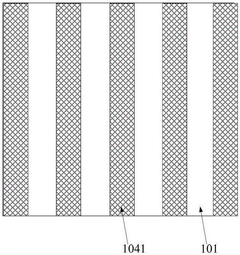
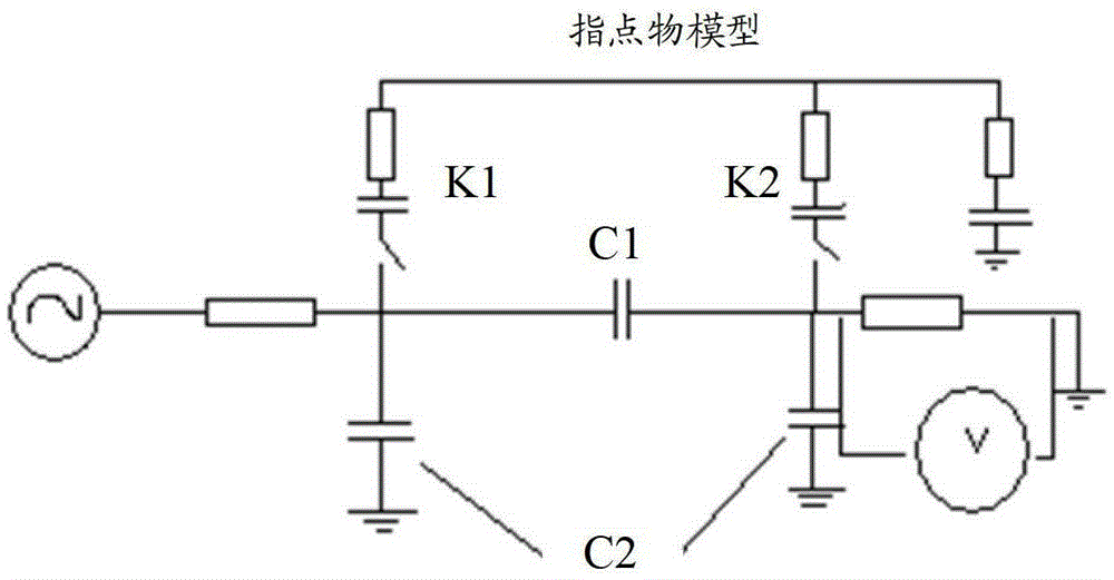
Provided are a liquid crystal cell and a 3D display device and a control method thereof. The liquid crystal cell (10) comprises: a first substrate (101), a second substrate (102), and a liquid crystal layer (103) located between the two substrates; a grating layer (104) located on the first substrate (101), and a touch electrode layer (105) located on the second substrate (102); and a second polarizing sheet (32) and a third polarizing sheet (33) respectively located on sides of the first substrate (101) and the second substrate (102) opposite to the liquid crystal layer (103). By using the structure, in a time-sharing cycle of a 3D display mode, a driving voltage is exerted on the touch electrode layer (105) and the grating layer (104) sequentially, and touch driving and grating driving are sequentially performed; in the gating driving process, the touch electrode layer (105) is grounded as a public electrode layer of the grating layer (104); and in the touch driving process, the grating layer (104) is grounded. Electrodes on the touch electrode layer (105) serve as touch electrodes of a touch module, and on the basis of ensuring that detection is performed for a touch signal once, a time for the touch driving process is shorter than a retention time of a liquid crystal molecule, so that both a grating light-splitting function and a touch control function are implemented in 3D display, thereby saving two layers of glass substrates.

Description

technical field [0001] The invention belongs to the field of 3D liquid crystal display, and in particular relates to a liquid crystal box, a 3D touch display device and a control method thereof. Background technique [0002] With the rapid development of display technology, people can no longer be satisfied with two-dimensional (TwoDimension, 2D) display screens, but need three-dimensional (ThreeDimension, 3D) stereoscopic display devices to provide more comprehensive information with a sense of depth . After more than ten years of development, 3D display technology has achieved very fruitful results. There have been devices capable of 3D imaging such as handheld observers, 3D stereoscopic glasses, and helmet displays. Up to now, the latest ones that do not need glasses Glasses-free 3D display using technical solutions such as prisms, lenses, gratings, and electronic switches. [0003] The 3D display is mainly based on the principle of human vision to obtain two images of ...

Claims


Application Information

Patent Timeline
Patent Type & Authority Patents(China)
IPC IPC(8): G02F1/133G02F1/1335G02F1/1343G02B27/22G06F3/041H04N13/00
CPCG02B30/25G02F1/13338G02F1/13471G06F3/0412G06F3/0443
Inventor 吴章奔马骏牛磊汪星辰
Owner SHANGHAI TIANMA MICRO ELECTRONICS CO LTD
Learn More