A Signal Conduction and Antenna Debugging Method

A debugging method and signal conduction technology, applied in the field of communication, can solve the problems of too long impedance lines, signal conduction and antenna debugging effects, and achieve the effect of avoiding influence and high radiation index.

Active Publication Date: 2015-08-26
BYD CO LTD
View PDF14 Cites 0 Cited by
  • Summary
  • Abstract
  • Description
  • Claims
  • Application Information

AI Technical Summary

Problems solved by technology

[0004] The purpose of the present invention is to provide a signal conduction and antenna debugging method to solve the technical problem in the prior art that the impedance line is too long to cause the impact on signal conduction and antenna debugging, so that it can still meet the high requirements under the harsh environment. Radiation indicators made possible

Method used


Image

  • A Signal Conduction and Antenna Debugging Method

Examples


Embodiment Construction

[0009] In order to make the technical problems, technical solutions and beneficial effects solved by the present invention clearer, the present invention will be further described in detail below in conjunction with the embodiments. It should be understood that the specific embodiments described here are only used to explain the present invention, not to limit the present invention.

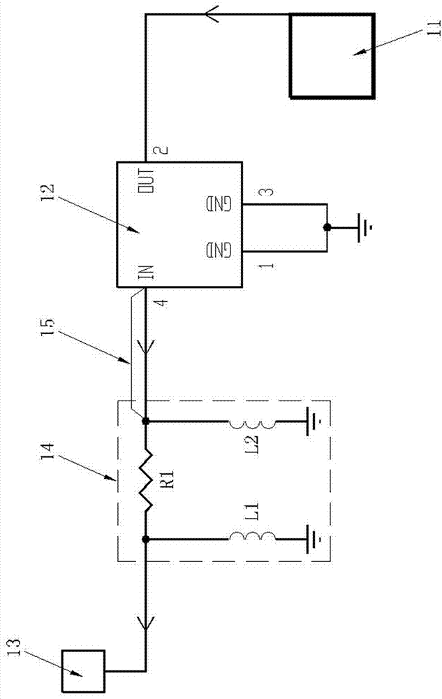
[0010] Please refer to figure 1 As shown, a signal conduction and antenna debugging method, the signal is output from the chip 11 to the signal test device (not shown in the figure) connected to the front end (port 2) of the signal processor 12, the antenna 13 is sequentially connected to the antenna The matching network 14, the impedance line 15 are connected to the antenna debugging device (not shown in the figure) connected to the rear end (port 4) of the signal processor 12, the debugging method disconnects the signal processor 12, and uses the signal testing device The front end of the sign...


PUM


Abstract

The invention provides a method for debugging signal transduction and an antenna. A signal is outputted to a signal test device connected with the front end of a signal processor through a chip. The antenna is sequentially connected with an antenna matching network, an impedance line and an antenna debugging device connected with the rear end of the signal processor. According to the method, the signal processor is disconnected, the signal is guided from the front end of the signal processor by means of the signal test device after the signal is outputted by the chip, transduction debugging is carried out, and the antenna debugging device carries out antenna debugging at the rear end of the signal processor. According to the method for debugging the signal transduction and the antenna, the impedance line is taken to be matched with the antenna to coordinate the debugging of the signal transduction and the antenna, influences of the impedance line are included, and the influences of the impedance line on the signal transduction and the antenna are avoided.

Description

technical field [0001] The invention belongs to the field of communication, and in particular relates to a method for signal conduction and antenna debugging. Background technique [0002] With the development of mobile phones, the requirements for the omnidirectional radiation performance of mobile phones are getting higher and higher. The radiation performance of BLUETOOTH, WIFI, GPS, FM, etc., which were not required before, now have corresponding standards; The smaller and thinner the antenna, coupled with the influence of various metal parts, the antenna environment is getting worse and worse. In addition, due to the limitation of the mobile phone board type, in some cases, the impedance line has to be lengthened, or the impedance line can only go through the inner layer of the mobile phone PCB board, etc. These conditions seriously deteriorate the signal conduction performance, making BLUETOOTH / The WIFI signal cannot be effectively transmitted to the antenna after pa...

Claims


Application Information

Patent Timeline
Patent Type & Authority Patents(China)
IPC IPC(8): G01R31/00H04B17/12
Inventor 朱俊霍勇
Owner BYD CO LTD
Why Eureka
Try Eureka