Eureka AIR delivers breakthrough ideas for toughest innovation challenges, trusted by R&D personnel around the world.

Shock test device and method

An impact test and impact hammer technology, which is applied in the field of impact test equipment, can solve problems such as injury, inaccurate test results, and non-compliance with test standards.

Inactive Publication Date: 2013-09-11
OCEANKING DONGGUAN LIGHTING TECH +2
View PDF6 Cites 5 Cited by
  • Summary
  • Abstract
  • Description
  • Claims
  • Application Information

AI Technical Summary

Problems solved by technology

However, in the actual operation process of the laboratory at present, because the impact hammer is in free fall in the sleeve, it hits the point to be impacted. Since it is a sleeve, the impact hammer will bounce back after hitting the object during the impact process. , then drop it again, and hit the object again, which will repeatedly hit N times, so that the transparent part will be hit many times, and the test result will be inaccurate, and it will not meet the test standard.

Method used


Image

  • Shock test device and method
  • Shock test device and method
  • Shock test device and method

Examples


Embodiment Construction

[0033] In order to facilitate the understanding of the present invention, the present invention will be described more fully below with reference to the associated drawings. Preferred embodiments of the invention are shown in the accompanying drawings. However, the present invention can be embodied in many different forms and is not limited to the embodiments described herein. On the contrary, these embodiments are provided to make the understanding of the disclosure of the present invention more thorough and comprehensive.

[0034] It should be noted that when an element is referred to as being “fixed” to another element, it can be directly on the other element or there can also be an intervening element. When an element is referred to as being "connected to" another element, it can be directly connected to the other element or intervening elements may also be present. The terms "vertical," "horizontal," "left," "right," and similar expressions are used herein for purposes ...


PUM


Abstract

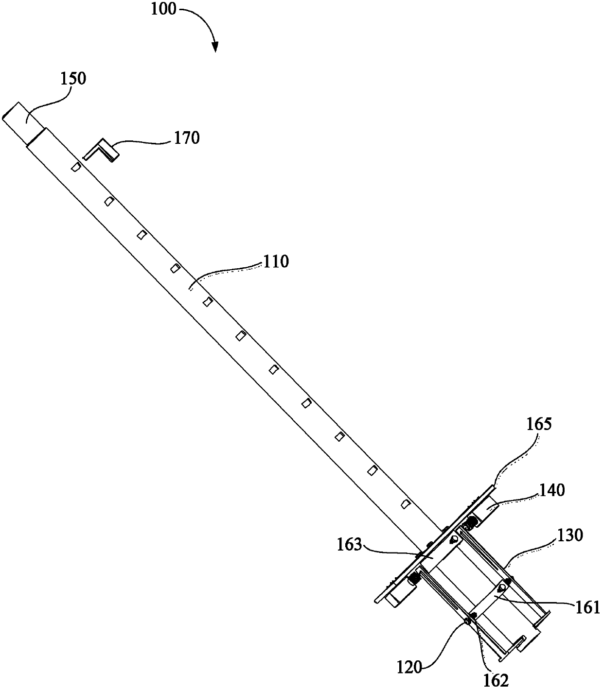
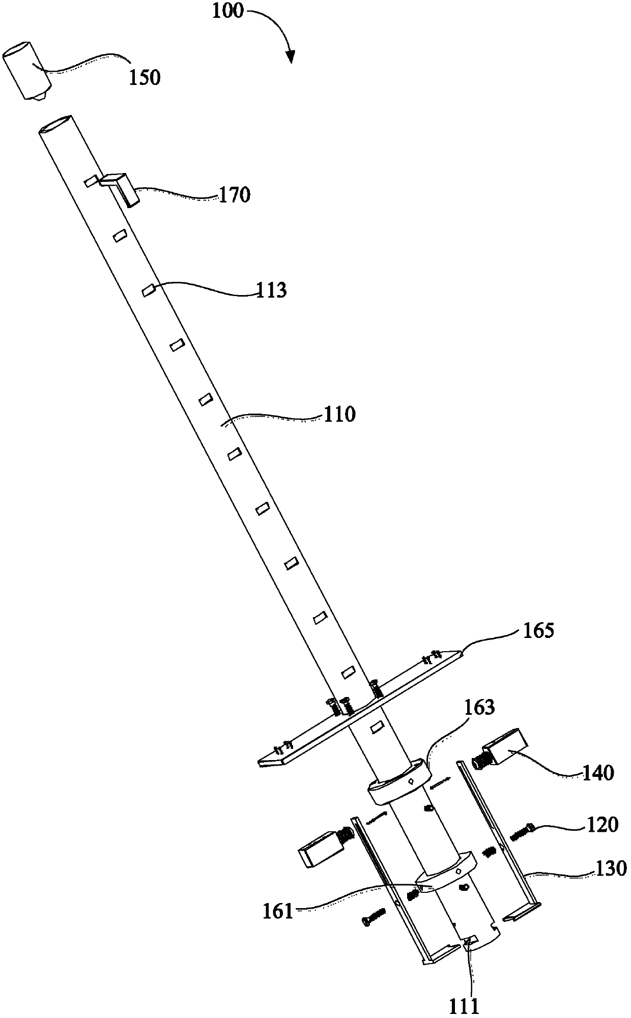
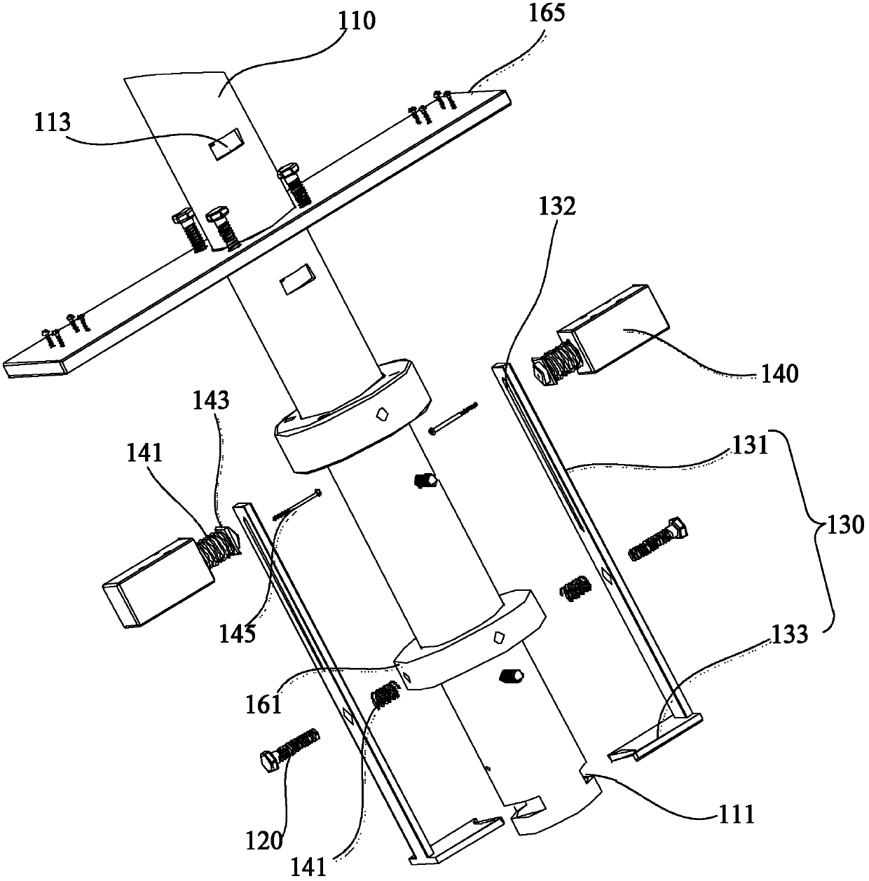
The invention discloses a shock test device which is characterized in that an insertion hole is formed in the side wall at one end of a sleeve, a supporting piece is fixed on the outer side wall of the sleeve, one end of a pulling rod can extend into the insertion hole, the middle of the pulling rod is movably connected with the supporting piece, a driving piece is fixedly connected with the other end of the pulling rod, and a shock hammer can enter the sleeve from one end, away from the insertion hole, of the sleeve and fall down from the other end of the sleeve. A photoelectric inductive assembly is arranged at one end, close to the insertion hole, of the sleeve. A control module is electrically connected with the driving piece and the photoelectric inductive assembly. When the shock hammer falls down from the sleeve, the photoelectric inductive assembly is triggered to generate an inductive signal on the control module. When the shock hammer rebounds again to enter the sleeve, the control module controls the driving piece to work, the driving piece drives the pulling rod to move relative to the supporting piece, and one end of the pulling rod extends into the insertion hole to intercept the shock hammer. The shock test device can protect the shock hammer against secondary shock. The invention further provides a shock test method.

Description

【Technical field】 [0001] The invention relates to a test device and method, in particular to an impact test device and method. 【Background technique】 [0002] In the usual test work in the laboratory, the strength of the lamp shell is often tested, and the impact test is used to investigate. There is such a regulation in the GB3836.1 standard: the glass transparent parts should be tested on three samples, and each sample is only Test once, other parts should be tested on two samples, and each sample should be tested once at two different positions. However, in the actual operation process of the laboratory at present, because the impact hammer is in free fall in the sleeve, it hits the point to be impacted. Since it is a sleeve, the impact hammer will bounce back after hitting the object during the impact process. , and then drop it again, and hit the object again, which will repeatedly hit N times, so that the transparent part will be hit many times, and the test result wi...

Claims


Application Information

Patent Timeline
Patent Type & Authority Applications(China)
IPC IPC(8): G01M7/08
Inventor 周明杰赵永川
Owner OCEANKING DONGGUAN LIGHTING TECH
Why Eureka
Eureka Blog
Learn More