Single-shaft rotary type inertial navigation system and special error self-compensation method thereof
An inertial navigation system and rotary technology, applied in the field of error compensation, can solve undiscovered problems, achieve the effect of improving compensation effect and guaranteeing maintenance cost
- Summary
- Abstract
- Description
- Claims
- Application Information
AI Technical Summary
Problems solved by technology
Method used
Image
Examples
Embodiment Construction
[0024] The present invention will be further described below in conjunction with accompanying drawing:
[0025] Explanation of serial numbers in the figure:
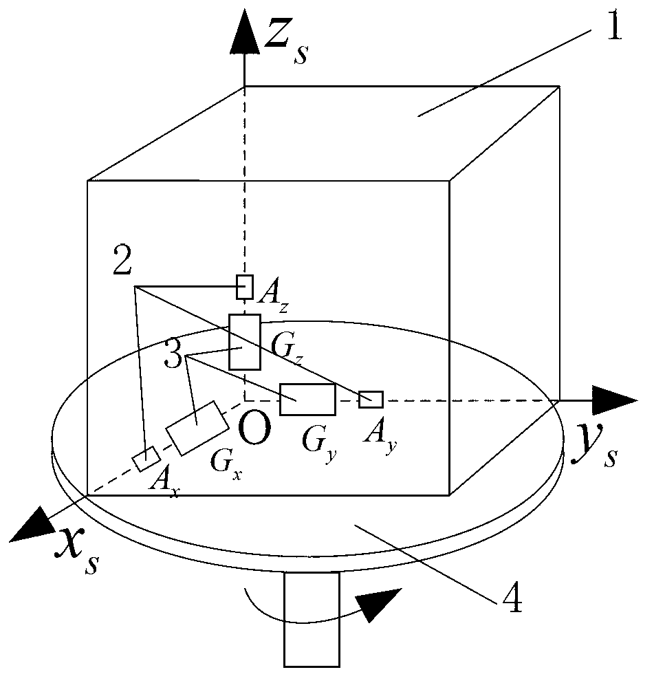
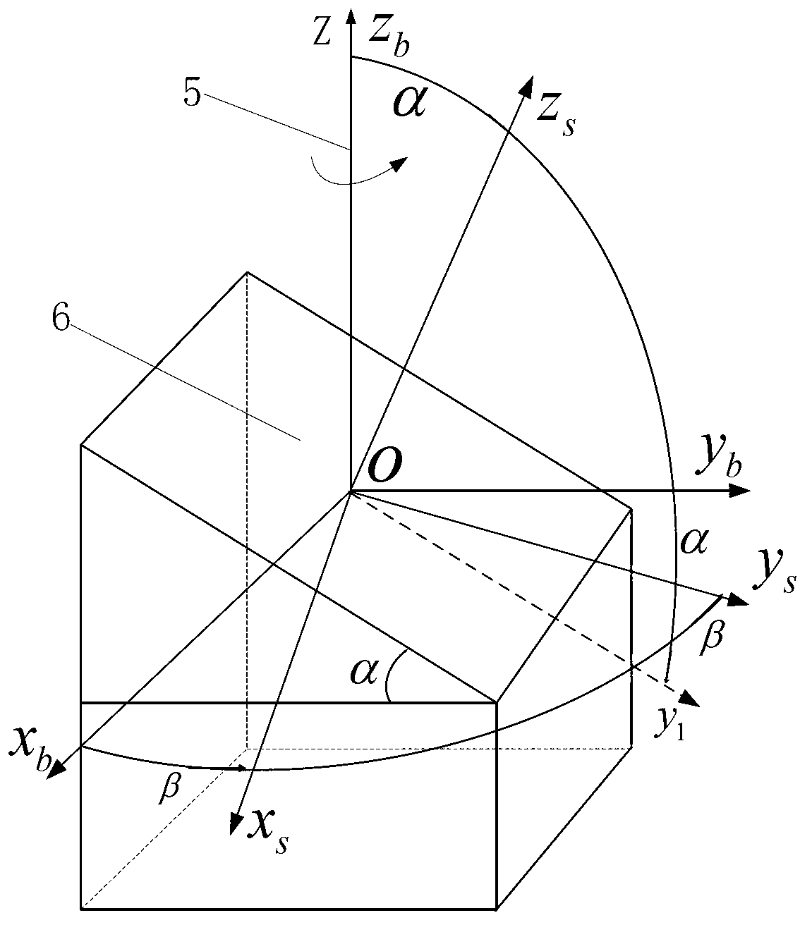
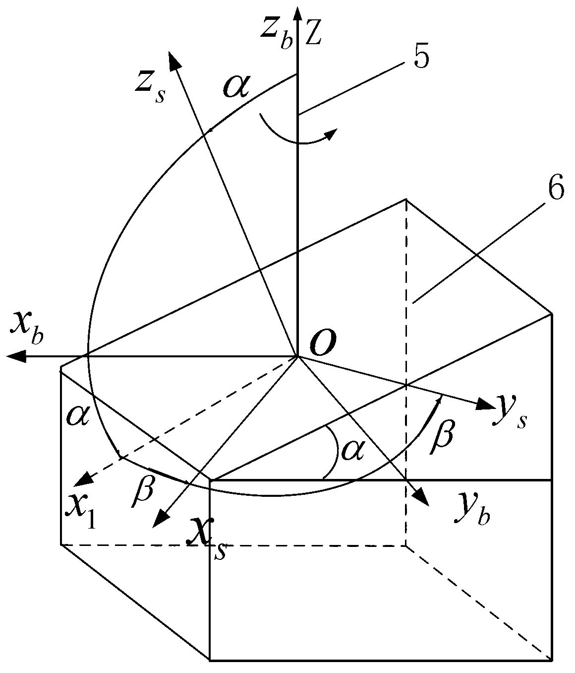
[0026] 1...IMU, 2...Three accelerometers, 3...Three gyroscopes, 4...Inversion mechanism, 5...Rotary shaft, 6...IMU mounting surface, 7...IMU output signal, 8...IMU mounting surface inclination adjustment mechanism Output signal, 9...CPU control inclination signal and inclination adjustment mechanism inclination monitoring signal, 10...Transposition mechanism rotation angle signal, 11...Transposition mechanism rotation angle signal and CPU control rotation angle signal.
[0027] The present invention is aimed at the fact that the current single-axis rotary inertial navigation system cannot compensate the constant value drift error and slow-variation random drift error of the inertial device in the direction parallel to the rotation axis, and the use of a two-axis or three-axis rotation scheme will make the system The ove...
PUM
 Abstract
Description
Claims
Application Information
 - R&D
- Intellectual Property
- Life Sciences
- Materials
- Tech Scout
- Unparalleled Data Quality
- Higher Quality Content
- 60% Fewer Hallucinations
Browse by: Latest US Patents, China's latest patents, Technical Efficacy Thesaurus, Application Domain, Technology Topic, Popular Technical Reports.
© 2025 PatSnap. All rights reserved.Legal|Privacy policy|Modern Slavery Act Transparency Statement|Sitemap|About US| Contact US: help@patsnap.com


