
AOI (Automated Optical Inspection) digital LED (Light-Emitting Diode) light source controller and control method thereof

A technology of LED light source and control method, applied in the direction of light source, electric light source, lighting device, etc., can solve the problems of insufficient image contrast, enlarged aperture, insufficient light source brightness, etc., and achieve the effect of clear image and precise brightness control

Inactive Publication Date: 2013-09-04
HUIZHOU VNICE ELECTRONICS TECH
View PDF7 Cites 10 Cited by
  • Summary
  • Abstract
  • Description
  • Claims
  • Application Information

AI Technical Summary

Problems solved by technology

Its main goal is to project light onto the object under test in a suitable way to maximize the contrast between the features to be observed and the image features to be ignored, while also ensuring sufficient overall brightness when the light source is not bright enough , there may be three bad situations: first, the signal-to-noise ratio of the camera is not enough; because the brightness of the light source is not enough, the contrast of the image must be insufficient, and the possibility of noise on the image will also increase
Secondly, if the brightness of the light source is not enough, the aperture must be increased, thereby reducing the depth of field; and when the brightness of the light source is not enough, the impact of random light such as natural light on the system will also increase

Method used


Image

  • AOI (Automated Optical Inspection) digital LED (Light-Emitting Diode) light source controller and control method thereof
  • AOI (Automated Optical Inspection) digital LED (Light-Emitting Diode) light source controller and control method thereof
  • AOI (Automated Optical Inspection) digital LED (Light-Emitting Diode) light source controller and control method thereof

Examples


Embodiment

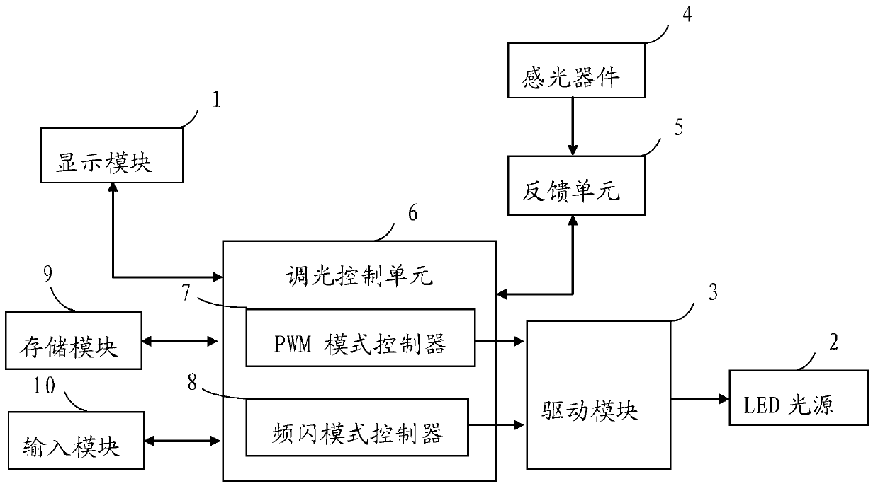
[0036] Such as figure 1 As shown, this embodiment provides an AOI digital LED light source controller, including:

[0037] The display module 1 is used to display the channel number of the LED light source 2 and the corresponding light source brightness value; the driving module 3 is used to drive the light source so that multiple LED light sources 2 are turned on sequentially; the photosensitive device 4 is used to receive signals from the sequentially turned on multiple LED light sources 2 light; the feedback unit 5 is used to generate a plurality of feedback signals based on the light receiving signal obtained by the photosensitive device 4 from the LED light source 2; the dimming control unit 6 is used to receive the plurality of feedback signals and generate a plurality of The pulse width modulation signal controls the driving module 3 to adjust the light emission of the running LEDs respectively, the photosensitive device 4 is connected to the feedback unit 5, and the di...


PUM


Abstract

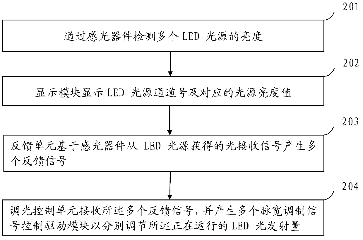
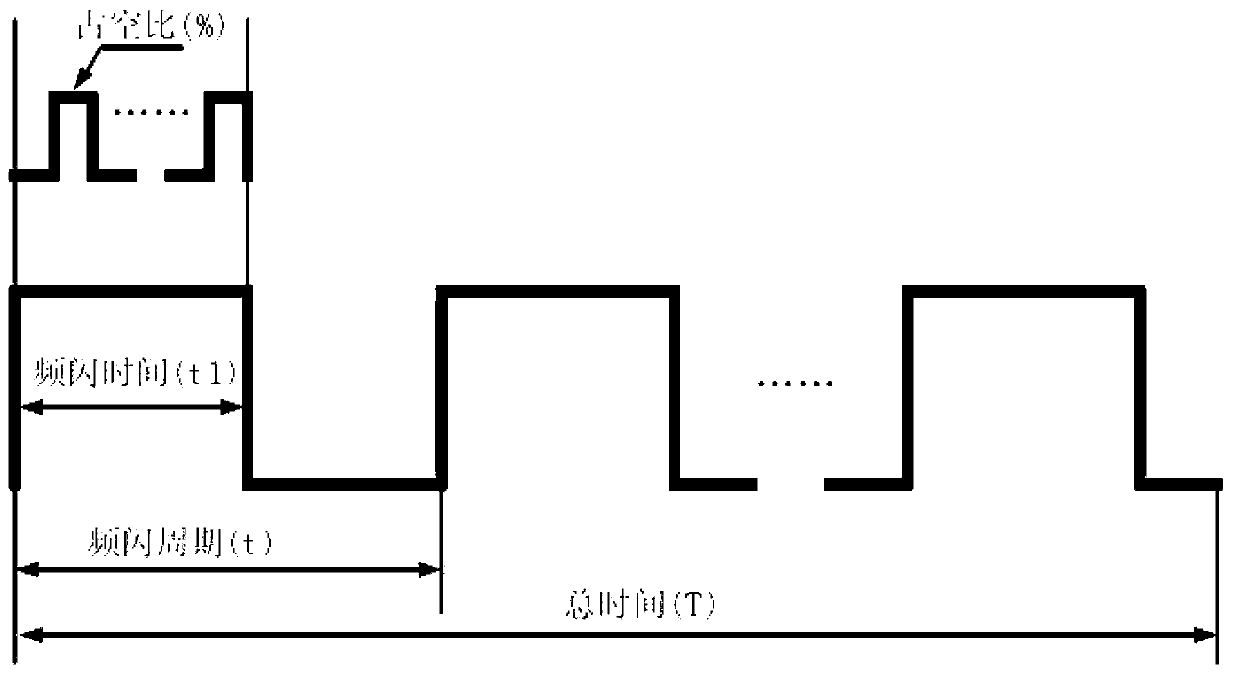
The invention discloses an AOI (Automated Optical Inspection) digital LED (Light-Emitting Diode) light source controller which comprises a display module, a driving module, a light sensor, a feedback unit and a dimming control unit, wherein the display module is used for displaying an LED light source channel number and a corresponding light source brightness value; the driving module is used for driving light sources so as to enable a plurality of LED light sources to be sequentially switched on; the light sensor is used for receiving light from the LED light sources which are sequentially switched on; the feedback unit is used for generating a plurality of feedback signals on the basis of light receiving signals which are obtained from the LED light sources by the light sensor; and the dimming control unit is used for receiving the plurality of feedback signals and generating a plurality of PWM (Pulse Width Modulation) signals to control the driving module so as to respectively regulate the light emitting quantities of running LEDs. The invention also provides an AOI digital LED light source control method. According to the invention, a PWM constant-current dimming manner is adopted; in the PWM dimming process, forward current conduction time is changed by switching on and switching off the LEDs so as to achieve a brightness regulating effect, ensure sufficient integral brightness and generate more excellent contrast between a feature which needs to be observed and an image feature which needs to be ignored.

Description

technical field [0001] The invention relates to a machine vision LED light source control device in the field of industrial automation, in particular to an AOI digital LED light source controller and a control method thereof. Background technique [0002] In order to meet the reliability requirements of PCB inspection, the best solution to comprehensively inspect PCB on the production line and complete repetitive, monotonous, and strict inspection tasks is to use the AOI (Automated optical inspection) system. The main function of AOI is to carry out comprehensive and strict inspection and quality control in the process of Surface Mounted Technology (SMT) on PCB boards, to find and eliminate defective products, so as to ensure product quality and save costs. Compared with other testing techniques, AOI can be used in multiple positions on the production line. Currently, it is mainly used in three processes: (1) Inspection after solder paste printing, timely detection of defect...

Claims


Application Information

Patent Timeline
IPC IPC(8): H05B37/02
Inventor 肖俊何高松
Owner HUIZHOU VNICE ELECTRONICS TECH
Learn More