Lamination device and lamination method for reactor iron core
A reactor and iron core technology, which is applied in the manufacture of inductors/transformers/magnets, circuits, electrical components, etc., can solve the problems of iron core column size, plane inconsistency, large air gap error, and insufficient flatness of the processed iron core, etc. problem, to achieve the effect of improving flatness, improving production efficiency and reducing air gap error
- Summary
- Abstract
- Description
- Claims
- Application Information
AI Technical Summary
Problems solved by technology
Method used
Image
Examples
Embodiment 1
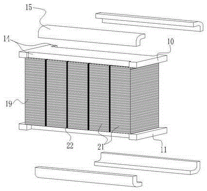
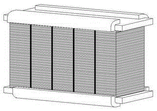
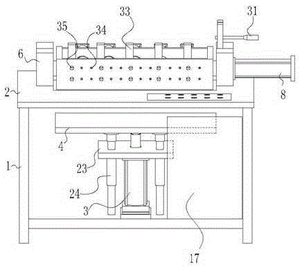
[0035] Embodiment 1: as Figure 3 to Figure 5 As shown, a lamination device for reactor cores includes a frame 1, a panel 2 arranged on the upper part of the frame 1, and a lower cylinder 3 arranged on the lower part of the frame 1, which is arranged on The flat plate 4 parallel to the panel 2 on the output shaft of the lower cylinder 3, the lamination frame 5 and the brackets 6 that are located on both sides and are rotatably connected to it, and are arranged on the lamination frame 5 for The vertical pressurized vertical cylinder 7 and the horizontal cylinder 8 arranged on the support 6, the output shaft of the horizontal cylinder 8 passes through the support 6 and the lamination frame side 27 from the lateral pressurization, and is arranged on The upper gusset splint 10 and the lower gusset splint 11 are used to clamp the iron core 9 to be processed in the lamination frame 5, and the panel 2 has a cavity 12 whose size matches the size of the flat plate 4. The flat plate 4 ...
Embodiment 2
[0052] Embodiment 2: Compared with Embodiment 1, the difference is only that: the acute angle slope 18 between the panel and the horizontal line is set to 7 degrees, and the bolts 31 are respectively inserted into the two bolt positioning holes 29 and the side positioning The lamination frame 5 is respectively fixed in the hole 30 at the position where the cross section of the lamination frame is perpendicular to the horizontal line and at the position where the cross section of the lamination frame and the cross section of the panel form an obtuse angle 36 of 100 degrees.
Embodiment 3
[0053] Embodiment 3: Compared with Embodiment 1, the difference is only that: the acute angle slope 18 between the panel and the horizontal line is set to 8 degrees, and the bolts 31 are respectively inserted into the two bolt positioning holes 29 and the side positioning The lamination frame 5 is fixed in the hole 30 at the position where the cross section of the lamination frame is perpendicular to the horizontal line and at the position where the cross section of the lamination frame and the cross section of the panel form an obtuse angle 36 of 110 degrees.
[0054]To sum up, the present invention adopts the electro-pneumatic principle, uses the vertical cylinder, the horizontal cylinder and the bottom cylinder to pressurize the processed iron core from three directions, so that the pressing force of each column of the processed iron core is consistent, Thereby ensuring the consistency of its size and plane, reducing the air gap error between the processed iron core columns,...
PUM
 Abstract
Description
Claims
Application Information
 - R&D
- Intellectual Property
- Life Sciences
- Materials
- Tech Scout
- Unparalleled Data Quality
- Higher Quality Content
- 60% Fewer Hallucinations
Browse by: Latest US Patents, China's latest patents, Technical Efficacy Thesaurus, Application Domain, Technology Topic, Popular Technical Reports.
© 2025 PatSnap. All rights reserved.Legal|Privacy policy|Modern Slavery Act Transparency Statement|Sitemap|About US| Contact US: help@patsnap.com


