
Visualization experiment device for deep cryogenic two-phase countercurrent process

A countercurrent process and experimental device technology, applied in measuring devices, fluid dynamics tests, instruments, etc., can solve problems such as the inability to observe the flow state of deep and low temperature fluids, and achieve the effect of solving pipeline sealing failure and wide temperature adaptation range

Inactive Publication Date: 2013-09-04
ZHEJIANG UNIV
View PDF6 Cites 15 Cited by
  • Summary
  • Abstract
  • Description
  • Claims
  • Application Information

AI Technical Summary

Problems solved by technology

However, neither of the above two devices can realize the function of observing the flow state of the deep cryogenic fluid, and the structure of the present invention is completely different.

Method used


Image

  • Visualization experiment device for deep cryogenic two-phase countercurrent process
  • Visualization experiment device for deep cryogenic two-phase countercurrent process
  • Visualization experiment device for deep cryogenic two-phase countercurrent process

Examples


Embodiment Construction

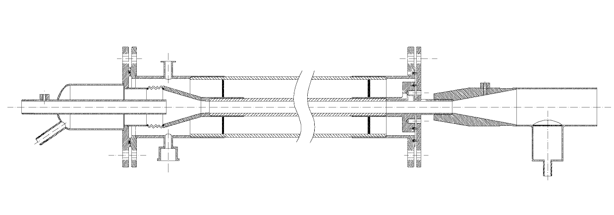
[0028] Such as figure 1 As shown, the visualization experimental device for the deep-low temperature two-phase countercurrent process includes a liquid collection section, a test section, a lower end surface Teflon gasket 5, a flange plate 19, a liquid inlet cone tube 20, and a Teflon gasket on the upper flange of the outer pipe. 23. Teflon gasket 24 of the connecting member on the small tube;

[0029] The liquid collection section includes a gas inlet pipe 1, a first pressure sensor 2, a liquid collector housing 3, an inner pipe lower flange 4, a liquid outlet pipe 26, and a transition piece 28. One end of the liquid collector housing 3 is provided with a head, The head is provided with a liquid outlet pipe 26, and the center of the liquid collector shell 3 is provided with a gas inlet pipe 1, which is fixed with the head of the liquid collector shell 3, and the other end of the liquid collector shell 3 is connected to the lower flange of the inner pipe. 4 are connected on ...


PUM


Abstract

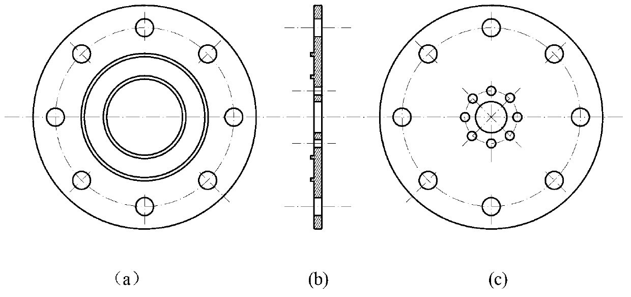
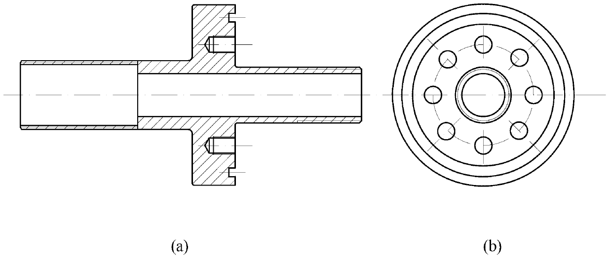
The invention discloses a visualization experiment device for a deep cryogenic two-phase countercurrent process. The visualization experiment device comprises a liquid collecting section, a testing section, a flange plate and a liquid inlet taper pipe, wherein the liquid collecting section is welded with an air inlet pipe and a liquid outlet pipe; inner and outer pipes in the testing section are two concentric transparent organic glass round pipes with different diameters, the inner pipe is a cryogenic fluid passageway, the upper end of the inner pipe is provided with a liquid inlet, and the lower end of the inner pipe is provided with a gas inlet; and an interlayer between the inner pipe and the outer pipe is vacuumized for heat insulation. The two ends of the outer pipe are connected with metal flanges, the upper end of the inner pipe is connected with a flange, and the lower end of the inner pipe is sequentially connected with a horn-shaped metal connection component and a corrugated pipe. The corrugated pipe is welded with a flange of the liquid collecting section through a transition member. The flange surfaces of the upper ends of the two pipes are level, and the flange surfaces of the lower ends of the two pipes and the flange surface of the liquid collecting section are sealed through polytetrafluoroethylene gaskets and bolts. A cylindrical metal liquid reservoir is welded onto the other side of the lower flange of the inner pipe, and is coaxial to and communicated with the inner pipe. According to the visualization experiment device for the deep cryogenic two-phase countercurrent process, the visualization of the deep cryogenic two-phase countercurrent process can be realized, and deep cryogenic vacuum insulation problem can be solved.

Description

technical field [0001] The invention relates to a low-temperature fluid flow experiment device, in particular to a visualization experiment device for a deep-low temperature two-phase countercurrent process. Background technique [0002] Today's large-scale air separation systems generally use structured packing columns instead of tray columns to realize the heat and mass transfer process between vapor and liquid. In the structured packing tower, the liquid air flows downward in the form of a liquid film along the surface of the packing under the action of gravity, while the low-temperature gas flows upward along the gap between the packing and the liquid film, forming a countercurrent flow with the liquid. When the relative speed of the two reaches a certain value, the flooding phenomenon is caused, that is, part or all of the downward liquid is taken away by the upward gas, and the pressure drop of the gas rises sharply. The flooding phenomenon is the main factor limiting...

Claims


Application Information

Patent Timeline
IPC IPC(8): G01M10/00
Inventor 张小斌陈建业姚蕾张伟邱利民熊炜朱佳凯
Owner ZHEJIANG UNIV
Learn More