Robot control system and method based on principal and subordinate teleoperation mechanical arm
A technology of main manipulator and control method, applied in manipulators, program-controlled manipulators, manufacturing tools, etc., which can solve problems such as difficult operation and inability to realize multi-axis linkage of manipulators
- Summary
- Abstract
- Description
- Claims
- Application Information
AI Technical Summary
Problems solved by technology
Method used
Image
Examples
Embodiment 1
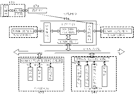
[0058] like figure 1 As shown, this robot control system based on the master-slave teleoperation manipulator includes master manipulator and information acquisition board (1), monitoring center PC (2), robot main control board (3), slave manipulator and FPGA motion control board (4), on-site environmental information collection board (5). The monitoring center PC (2) is connected to the main mechanical arm and the information acquisition board (1), and the monitoring center PC (2) is connected to the robot main control board (3) through wireless network communication, and the robot main control board (3) is connected through the CAN bus From the mechanical arm and FPGA motion control board (4), on-site environmental information collection board (5).
[0059] The main mechanical arm and the information acquisition board (1) refer to the main arm manually operated by the operator in the system, and the acquisition board of the angle information of each joint of the main ...
Embodiment 2
[0062] like image 3 As shown, it is the operating field hardware platform, including the robot main control board, FPGA motion control board and sensor information acquisition board. As the main control module, the main control board is an ARM development board equipped with embedded Linux. The development board is equipped with a USB camera, a USB wireless network card, and a CAN bus controller MCP2510. The USB camera completes the job site video collection, and the USB wireless network card completes Through WIFI, it communicates with the monitoring center PC or on-site wireless router. The MCP2510 controller accesses the CAN bus through the CAN bus transceiver, and communicates with the two external modules. In the embedded Linux operating system, in addition to transplanting the camera driver and wireless network card driver, the open source video codec library xvidcore and the real-time transmission library jrtplib are also transplanted, which are responsible for vid...
Embodiment 3
[0085] like Image 6 , Figure 7 Shown is the experimental part of Experimental Example 2, that is, the functional verification part.
[0086] like Image 6 Shown is a screenshot of the control panel of the monitoring center written based on MFC. As shown in the figure, the control panel generally includes video display, control panel operation, sub-module operation, robot position display, on-site robot IP address input, sensor switch, on-site environmental information and vehicle body status display. After the communication is established, the operator can manually operate the master manipulator to complete the control of the slave manipulator, and the operation screen of the job site can be transmitted to the control panel through video. It can be displayed in the control panel in real time. The operator can also shut down parts such as the main control board, the sensor information acquisition board, and each sensor module as required.
[0087] like Figu...
PUM
 Abstract
Description
Claims
Application Information
 - Generate Ideas
- Intellectual Property
- Life Sciences
- Materials
- Tech Scout
- Unparalleled Data Quality
- Higher Quality Content
- 60% Fewer Hallucinations
Browse by: Latest US Patents, China's latest patents, Technical Efficacy Thesaurus, Application Domain, Technology Topic, Popular Technical Reports.
© 2025 PatSnap. All rights reserved.Legal|Privacy policy|Modern Slavery Act Transparency Statement|Sitemap|About US| Contact US: help@patsnap.com


