A thermal spray tooling

A technology of thermal spraying and tooling, applied in the direction of workpiece clamping device, metal material coating process, coating, etc., can solve the problems of increasing labor intensity of operators, redundant actions of operators, and clamping can not be completed in one step, etc. Achieve the effects of reducing redundant actions, easy installation, and practical functions

Active Publication Date: 2016-05-25
中内凯思汽车新动力系统有限公司
View PDF5 Cites 0 Cited by
  • Summary
  • Abstract
  • Description
  • Claims
  • Application Information

AI Technical Summary

Problems solved by technology

[0002] At present, the thermal spraying tooling used in the workshop cannot be set up in one step, and the operator has many redundant actions, which increases the labor intensity of the operator

Method used


Image

  • A thermal spray tooling

Examples


Embodiment

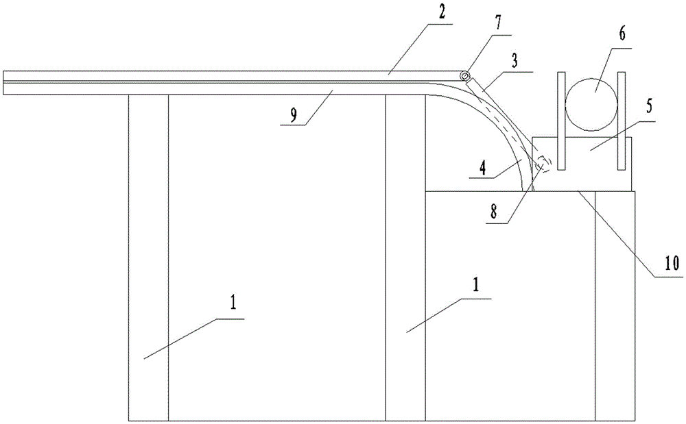
[0009] Example: such as figure 1 Shown, a kind of thermal spraying tooling comprises support 1, and guide rail is provided with on support 1, and guide rail comprises horizontal guide rail 9 and the arc guide rail 4 of docking, and the end of arc guide rail 4 is provided with horizontal support platform 10; There is a guide rod, the guide rod includes a horizontal rod 2 and a hinged rotating rod 3, the outer end of the horizontal rod 2 is connected to the output end of the hydraulic press, and the power is provided by the hydraulic press to pull the fixture and the workpiece. The outer end of the rotating rod 3 is hinged with the fixture 5, and the inner side of the fixture 5 is attached to the arc guide rail 4, and the workpiece 6 is clamped on the opening of the fixture 5; when the fixture 5 passes through the arc guide rail 4 from top to bottom, the opening direction of the fixture 5 is determined by The horizontal direction becomes vertical upwards. The horizontal rod 2 a...


PUM

PropertyMeasurementUnit
angleaaaaaaaaaa

Abstract

The invention relates to a thermal spraying tool which comprises a supporting frame. A guiding rail is arranged on the supporting frame and comprises a horizontal guiding rail and an butted arc guiding rail. A horizontal supporting frame platform is arranged at the tail end of the arc guiding rail. A guiding rod is arranged on the guiding rail. The guiding rod comprises a horizontal rod and a revolving rod hinged to the horizontal rod. The outer end of the horizontal rod is in transmission connection with the output end of an oil press. The outer end of the revolving rod is hinged to a clamp. The inner side of the clamp is adhered to the guiding rail. A workpiece is clamped on an opening of the clamp. When the clamp goes through the arc guiding rail from top to bottom, the opening of the clamp becomes vertical instead of being horizontal. The horizontal rod and the revolving rod are connected through a first pin. The revolving rod and the clamp are connected through a second pin. A central angle of the arc guiding rail is 90 degrees. Redundant actions of operators are reduced and the workpiece is convenient to install.

Description

technical field [0001] The invention relates to a thermal spraying tool. Background technique [0002] At present, the thermal spraying tooling used in the workshop cannot be clamped in one step, and the operator has many redundant actions, which increases the labor intensity of the operator. Contents of the invention [0003] The invention provides a thermal spraying tool, which facilitates the installation of workpieces. [0004] In order to solve the above technical problems, the present invention adopts the following technical scheme: a thermal spraying tooling, including a bracket, a guide rail is provided on the bracket, and the guide rail includes a horizontal guide rail and a docked arc guide rail, and a horizontal support platform is provided at the end of the arc guide rail ;There is a guide rod on the guide rail. The guide rod includes a horizontal rod and a hinged rotating rod. The outer end of the horizontal rod is connected to the output end of the hydraulic...

Claims


Application Information

Patent Timeline
Patent Type & Authority Patents(China)
IPC IPC(8): B25B11/00C23C4/00C23C4/12
Inventor 王刚李晓艳张忠民孙俊卫周广辉刘栋
Owner 中内凯思汽车新动力系统有限公司
Why Eureka
Try Eureka