Low-torque valve switching device and application

A technology of valve switching and low torque, which is applied in the direction of valve devices, cocks including cut-off devices, engine components, etc. It can solve the problems of valve drive that cannot achieve low power consumption, large drive torque of the spool, and low cost, and achieve torque Small, easy to drive, and low-cost effects

Inactive Publication Date: 2013-08-28
HANGZHOU ENGRID TECH
View PDF6 Cites 0 Cited by
  • Summary
  • Abstract
  • Description
  • Claims
  • Application Information

AI Technical Summary

Problems solved by technology

[0003] In the prior art ball valve structure control valve, usually, the valve body and the valve core are filled with sealing material to ensure that the valve does not leak after the valve is closed. This sealing material forms the resistance when the valve core rotates, so that the valve The torque of the core drive is relatively large, and it is impossible to achieve low-power valve drive
[0004] With the development of heat metering for urban central heating, it is becoming more and more important to invent a control valve that can achieve low torque, reduce the power consumption of the drive, and solve the problem of power supply for control valves and heat meters with valves. In the prior art, there is no reliable, practical and low-cost solution

Method used


Image

  • Low-torque valve switching device and application
  • Low-torque valve switching device and application

Examples


Embodiment Construction

[0023] The present invention will be further described below in conjunction with the accompanying drawings.

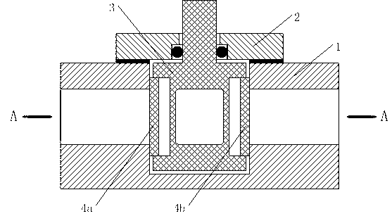
[0024] see figure 1 , is a cross-sectional view of an embodiment of the valve switch device of the present invention,

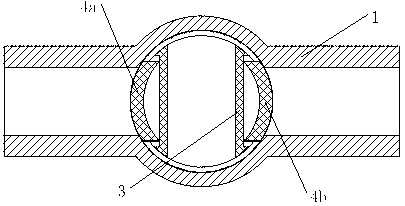
[0025] This embodiment includes a valve body 1, a valve cover 2, a valve core 3, a first blocking piece 4a, and a second blocking piece 4b. The valve body 1 and the valve cover 2 form a cylindrical valve cavity with top and left and right openings, and the valve core 3 is located in the valve cavity. The middle part of the spool 3 is provided with a horizontal through hole connecting the left and right openings; the horizontal sides of the spool 3 perpendicular to the opening direction of the through hole are respectively provided with grooves; the first baffle 4a and the second baffle 4b are respectively located In the grooves on both sides of the core 3.

[0026] The valve core 3 includes a rotating shaft at the top, and the rotating shaft is loc...


PUM


Abstract

The invention discloses a low-torque valve switching device and application. The low-torque valve switching device comprises a valve body, a valve cover, a valve core and a first stopping sheet, wherein the valve body and the valve cover form a valve cavity, openings are formed in the top, the left side and the right side of the valve cavity respectively, the valve core is located in the valve cavity, the valve core can rotate, and a horizontal through hole is formed in the valve core. A first groove is formed in the perpendicular direction of the horizontal through hole, and the arc-shaped first stopping sheet is located in the first groove. A second groove is formed in the perpendicular direction of the horizontal through hole of the valve core, the position of the second groove is opposite to that of the first groove, and a second stopping block is located in the second groove. The valve core further comprises a rotation shaft at the top, and the rotation shaft is located at an opening in the top of the valve cavity. The valve core is connected with a motor. The low-torque valve switching device can be used in low-power dissipation control valves, household calorimeters with valves and cold scales. The low-torque valve switching device is small in torque and easy to drive, effective switching-off of a valve is achieved by the arrangement of the stopping sheet, and the low-torque valve switching device is simple in structure, low in cost, strong in reliability, and applicable to long-distance control, electric control and large-scale application.

Description

technical field [0001] The valve switch device of the present invention relates to the field of control valves, in particular to the field of low power consumption control valves requiring battery power, such as heat metering and cold metering. The invention is suitable for battery-powered control valves, low-power consumption control valves, household heat meters and cold meters with valves, and the like. Background technique [0002] The control valve generally drives the valve through the rotation of the motor, so as to realize the opening and closing of the valve. There are many types of valves, such as ball valves, butterfly valves, gate valves, etc. [0003] In the prior art ball valve structure control valve, usually, the valve body and the valve core are filled with sealing material to ensure that the valve does not leak after the valve is closed. This sealing material forms the resistance when the valve core rotates, so that the valve The torque of the cor...

Claims


Application Information

Patent Timeline
IPC IPC(8): F16K5/14F16K37/00
Inventor 丁云李资庭
Owner HANGZHOU ENGRID TECH
Why Eureka
Try Eureka