
Sinking pump automatic control device and control method thereof

An automatic control device and submersible pump technology, applied in pump control, machine/engine, liquid variable volume machinery, etc., can solve the problem of difficulty in controlling the start and stop time of submersible pumps, and avoid waste of personnel and eliminate accidents. Effect

Inactive Publication Date: 2013-08-28
CHINA COAL ENERGY HEILONGJIANG COAL CHEM
View PDF8 Cites 3 Cited by
  • Summary
  • Abstract
  • Description
  • Claims
  • Application Information

AI Technical Summary

Problems solved by technology

[0003] The purpose of the present invention is to solve the problem of difficult control of manual control and submersible pump start and stop time, and provide an automatic submersible pump control device and a control method for the device

Method used


Image

  • Sinking pump automatic control device and control method thereof
  • Sinking pump automatic control device and control method thereof

Examples


specific Embodiment approach 1

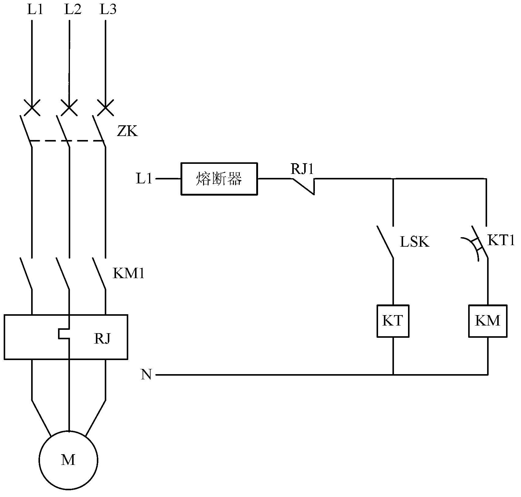
[0018] Specific implementation mode one: combine figure 1 Describe this embodiment, the submersible pump automatic control device described in this embodiment includes a submersible pump, a water level limiter, an AC contactor, a fuse, a time relay and a thermal relay, and the control coil KT of the time relay is connected to the water level limiter. The limit switch LSK of the meter is connected in series to form the first series branch, and the coil KM of the AC contactor is connected in series with the delay normally open contact KT1 of the time relay to form the second series branch, and the second series branch is connected in series with the first series branch. The branches are connected in parallel to form a parallel branch, and the parallel branch is connected in series with the normally closed contact RJ1 of the thermal relay and the fuse between any live wire and the neutral wire of the power supply circuit of the three-phase AC motor M of the submersible pump. The ...

specific Embodiment approach 2

[0020] Specific implementation mode two: combination figure 1 Describe this embodiment. The difference between this embodiment and the submersible pump automatic control device described in Embodiment 1 is that the device also includes an air switch ZK, which is connected in series to the power supply of the three-phase AC motor M of the submersible pump. in the loop.

specific Embodiment approach 3

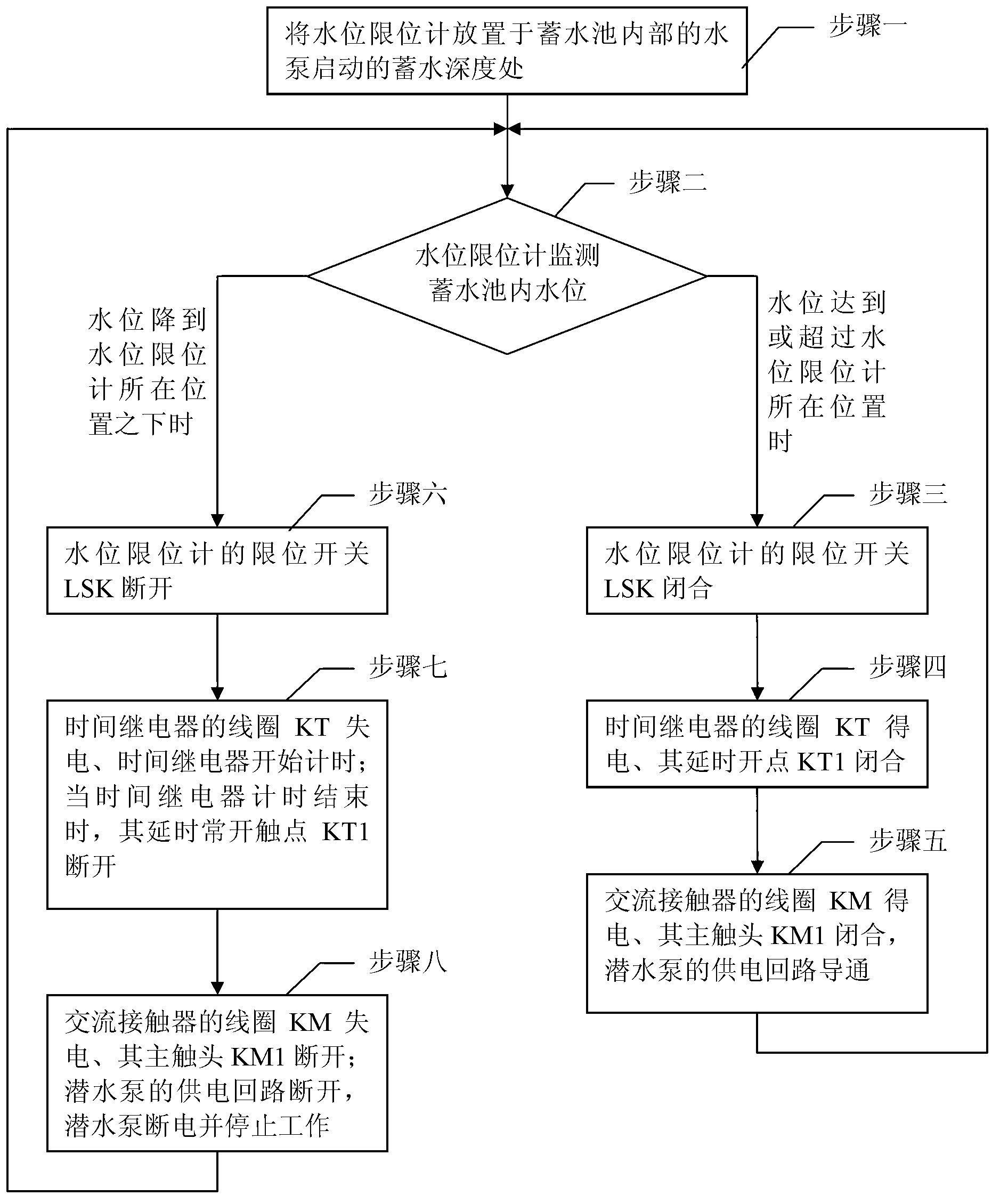
[0021] Specific implementation mode three: combination figure 2 This embodiment is described. This embodiment is based on the control method of the submersible pump automatic control device described in Embodiment 1. The control method is implemented through the following steps:

[0022] Step 1. Place the water level limiter at the water storage depth where the water pump inside the reservoir starts; perform step 2;

[0023] Step 2. The water level limit gauge monitors the water level in the reservoir. When the water level reaches or exceeds the position of the water level limit gauge, perform step 3; when the water level drops below the position of the water level limit gauge, perform step 6;

[0024] Step 3, the limit switch LSK of the water level limit gauge is closed, and step 4 is performed;

[0025] Step 4, the coil KT of the time relay is energized, and its time-delay normally open contact KT1 is closed; perform step 5;

[0026] Step 5: The coil KM of the AC contacto...


PUM


Abstract

The invention discloses a sinking pump automatic control device and a control method of the sinking pump automatic control device and relates to the technical field of sinking pump automatic control. The sinking pump automatic control device comprises a sinking pump, a water level limiting gauge, an alternating current contactor, a fuse protector, a time relay and a heat relay. The time relay is in series connection with a limiting switch of the water level limiting gauge. A coil of the alternating current contactor is in series connection with a delaying normally open contact of the time relay. After two series branches are connected in parallel, a normally closed contact of the heat relay and the fuse protector are in series connection between any firing line and a null line of a supply circuit of a three-phase alternating current motor of the sinking pump. A main contact of the alternating current contactor and a coil of the heat relay are in series connection in a supply loop of the three-phase alternating current motor. When a water level rises to the level higher than that of the water level limiting gauge, the limiting switch is switched off and the sinking pump starts to operate. When the water level drops to the level lower than that of the water level limiting gauge, the time delay starts to time, and the sinking pump stops operating after timing is end. The sinking pump automatic control device has the advantage of automatically controlling the sinking pump and is suitable for being used in basements with water seepage or water leakage.

Description

technical field [0001] The invention relates to an automatic control technology of a submersible pump. Background technique [0002] The basement of the high-voltage room of many substations seeps water all the year round due to design defects during construction (it cannot be remedied), especially during the flood season every year. The large amount of water seepage poses a great safety hazard to the normal operation of high-voltage 6kv equipment. A submersible pump is built in a reservoir, and a magnetic starter is used on the ground to manually control the start and stop of the submersible pump. The submersible pump control device that manually controls the start and stop of the submersible pump has certain defects, and it is difficult to control the drainage time (the amount of water seepage has uncertain factors). Overflow or submersible pump without water operation burns the submersible pump (the motor is cooled by water when the submersible pump is running) is a man-...

Claims


Application Information

Patent Timeline
Patent Type & Authority Applications(China)
IPC IPC(8): F04B49/06
Inventor 孙维新
Owner CHINA COAL ENERGY HEILONGJIANG COAL CHEM
Learn More