
Plunger pump valve rubber press-in equipment

A plunger pump and rubber technology, which is applied in the field of plunger pump valve rubber pressing equipment, can solve problems affecting the performance of parts, no guide device, and valve rubber strain, so as to improve efficiency, protect valve rubber, and improve assembly efficiency effect

Inactive Publication Date: 2013-08-28
SHANDONG VICTOR OILFIELD EQUIP
View PDF6 Cites 8 Cited by
  • Summary
  • Abstract
  • Description
  • Claims
  • Application Information

AI Technical Summary

Problems solved by technology

[0003] 1. There is no guiding device, and the valve rubber is tilted during the assembly process, causing local strain or damage to the valve rubber;
[0004] 2. Two to three people are required during the assembly process, and manual tapping of the tooling is required to install the valve rubber into the valve body;
[0005] 3. There is no axial positioning during assembly, and it is easy to damage the valve rubber mounting surface of the valve body when knocking and installing, which will affect the performance of parts

Method used


Image

  • Plunger pump valve rubber press-in equipment
  • Plunger pump valve rubber press-in equipment
  • Plunger pump valve rubber press-in equipment

Examples


Embodiment Construction

[0028] Embodiments of the present invention are further described below in conjunction with accompanying drawings:

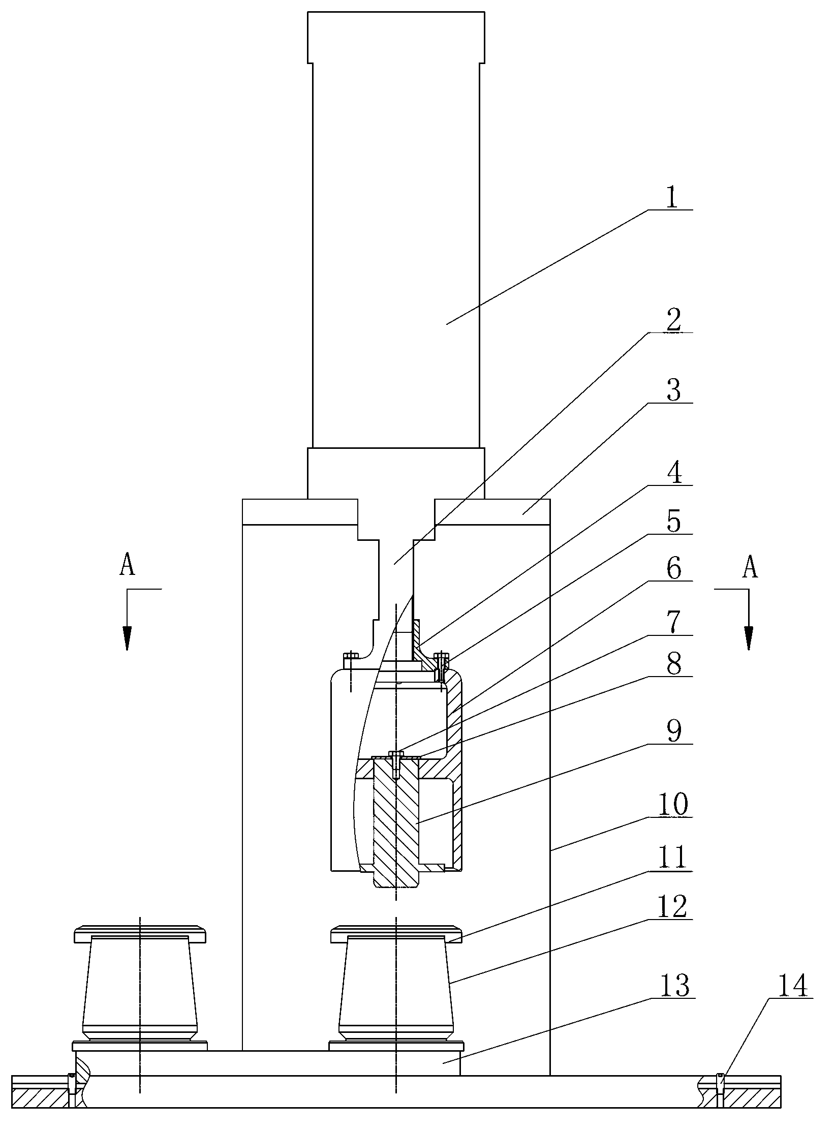
[0029] Such as Figure 1~3 As shown, the plunger pump valve rubber pressing equipment includes a workbench 10, a guide pressing mechanism, a valve body seat 13 and a taper sleeve 12 for assembling the valve rubber 11. The guide pressing mechanism is installed on the top of the workbench 10, corresponding to the guide A valve body seat 13 is installed on the lower part of the workbench 10 by the pressing mechanism, and a positioning hole for installing an inverted valve body 15 is set on the valve body seat 13, and the drogue sleeve 12 is sleeved on the inverted valve body 15 from above.

[0030] in:

[0031] The bottom of the workbench 10 is provided with a guide rail 16, the bottom of the valve body seat 13 is provided with a slide block cooperating with the guide rail 16, two positioning holes are arranged on the valve body seat 13 along the guide rail 16 dir...


PUM


Abstract

The invention belongs to the field of mechanical equipment, and particularly relates to plunger pump valve rubber press-in equipment. The plunger pump valve rubber press-in equipment is characterized by comprising a working table, a guiding downward-pressing mechanism, a valve seat and a taper sleeve for assembling valve rubber. The guiding downward-pressing mechanism is installed on the upper portion of the working table, the valve seat corresponding to the guiding downward-pressing mechanism is installed at the lower portion of the working table, positioning holes for installing an inverted valve body are formed in the valve seat, and the taper sleeve is sleeved on the inverted valve body from the upper portion of the inverted valve body. The plunger pump valve rubber press-in equipment is reasonable in structure, replaces the traditional mode that tools are manually knocked to put the valve rubber in the valve body, saves manpower, and improves assembly efficiency. The valve rubber is prevented from being deviated after being pressed through the guiding downward-pressing mechanism in the assembling process. Therefore, the valve rubber is effectively protected, and assembling quality is guaranteed. Because two positioning holes are formed in the valve seat, in the process that the valve rubber is pressed through the guiding downward-pressing mechanism, a well-assembled valve body and a well-assembled taper sleeve can be taken down, a valve body, a taper sleeve and valve rubber which are not well assembled are filled, and therefore time is fully utilized, and efficiency is improved.

Description

technical field [0001] The invention relates to a plunger pump valve rubber pressing device, which belongs to the field of mechanical equipment. Background technique [0002] The valve body (valve body) is a key part of the hydraulic end of the plunger pump. It consists of two parts. The valve body 1 is a precision steel casting. There are 4 claws, and the valve rubber 2 is polyurethane with relatively large Shore hardness. Together with the valve seat, spring and other accessories, it is used to control the suction and discharge of liquid in the hydraulic end. It can withstand a maximum pressure of 143Mpa. It is used in large quantities in cementing and fracturing operations in oil and gas fields. The currently used valve rubber loading devices generally have the phenomena of inconvenient operation, easy damage to parts, low assembly efficiency, and high labor intensity. The main reasons are as follows: [0003] 1. There is no guiding device, and the valve rubber is tilt...

Claims


Application Information

Patent Timeline
Patent Type & Authority Applications(China)
IPC IPC(8): B23P19/027
Inventor 王泽刚岳林李克雷魏光明汪军宗学国
Owner SHANDONG VICTOR OILFIELD EQUIP
Learn More