Eureka AIR delivers breakthrough ideas for toughest innovation challenges, trusted by R&D personnel around the world.

Fluidized vacuum dust collector

A vacuum suction and fluidization technology, applied in chemical instruments and methods, separation of dispersed particles, filtration of dispersed particles, etc., can solve the problem of increased resistance of the filter bag 3, difficulty in disassembling and replacing the filter bag 3, and failure of the filter bag 3 to be used normally And other problems, to achieve the effect of improving the efficiency of ash suction

Active Publication Date: 2015-08-05
苏州菲泰科过滤技术有限公司
View PDF6 Cites 0 Cited by
  • Summary
  • Abstract
  • Description
  • Claims
  • Application Information

AI Technical Summary

Problems solved by technology

[0003] However, in the process of use, it is often accompanied by friction and collision between the filter bag 3 and the cage and the internal components of the dust collector. Long-term friction and collision will cause damage to the filter bag 3
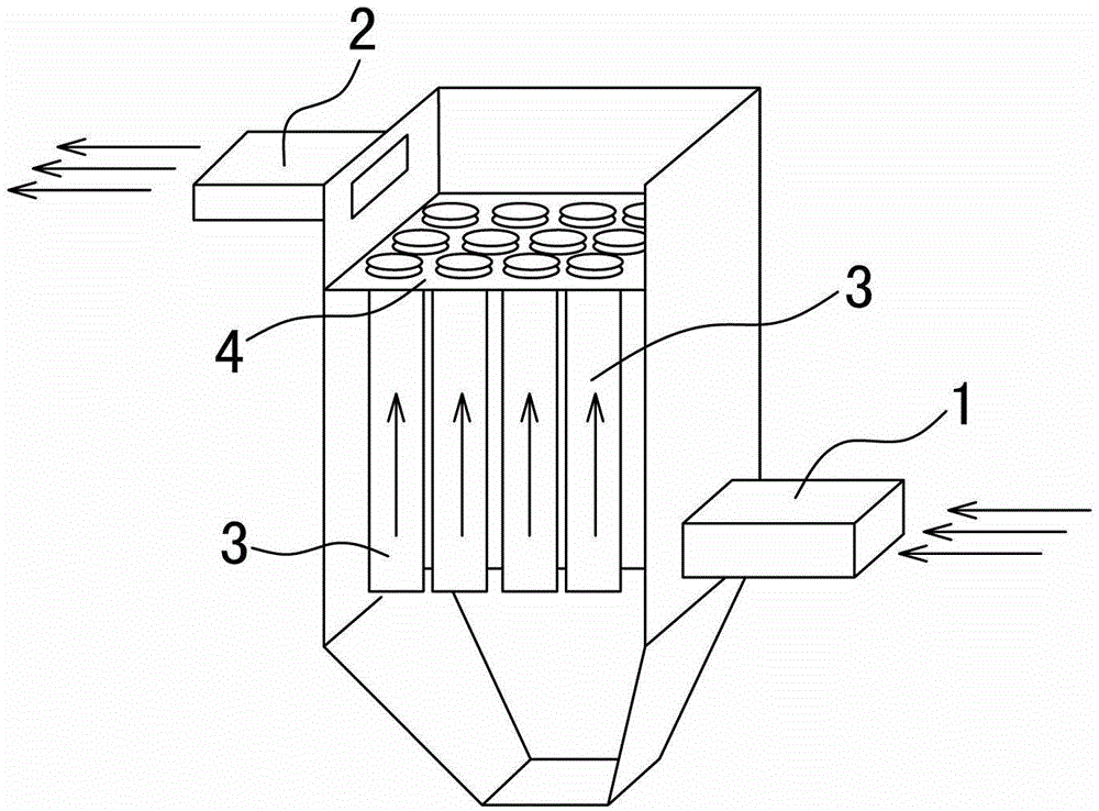
The smoke and dust in the flue gas directly pass through the damaged part of the filter bag 3 and reach the top of the flower plate 4, part of the smoke and dust are discharged into the atmosphere through the flue gas outlet 2 with the flue gas, part of the smoke and dust settle on the surface of the flower plate 4, and finally most of the smoke and dust enter the filter bag 3, serious even fills the entire filter bag, causing the resistance of the filter bag 3 to increase, resulting in the failure of the filter bag 3 to work normally, and making it difficult to disassemble and replace the filter bag 3

Method used


Image

  • Fluidized vacuum dust collector
  • Fluidized vacuum dust collector
  • Fluidized vacuum dust collector

Examples


Embodiment

[0029] Example: fluidized vacuum dust collector

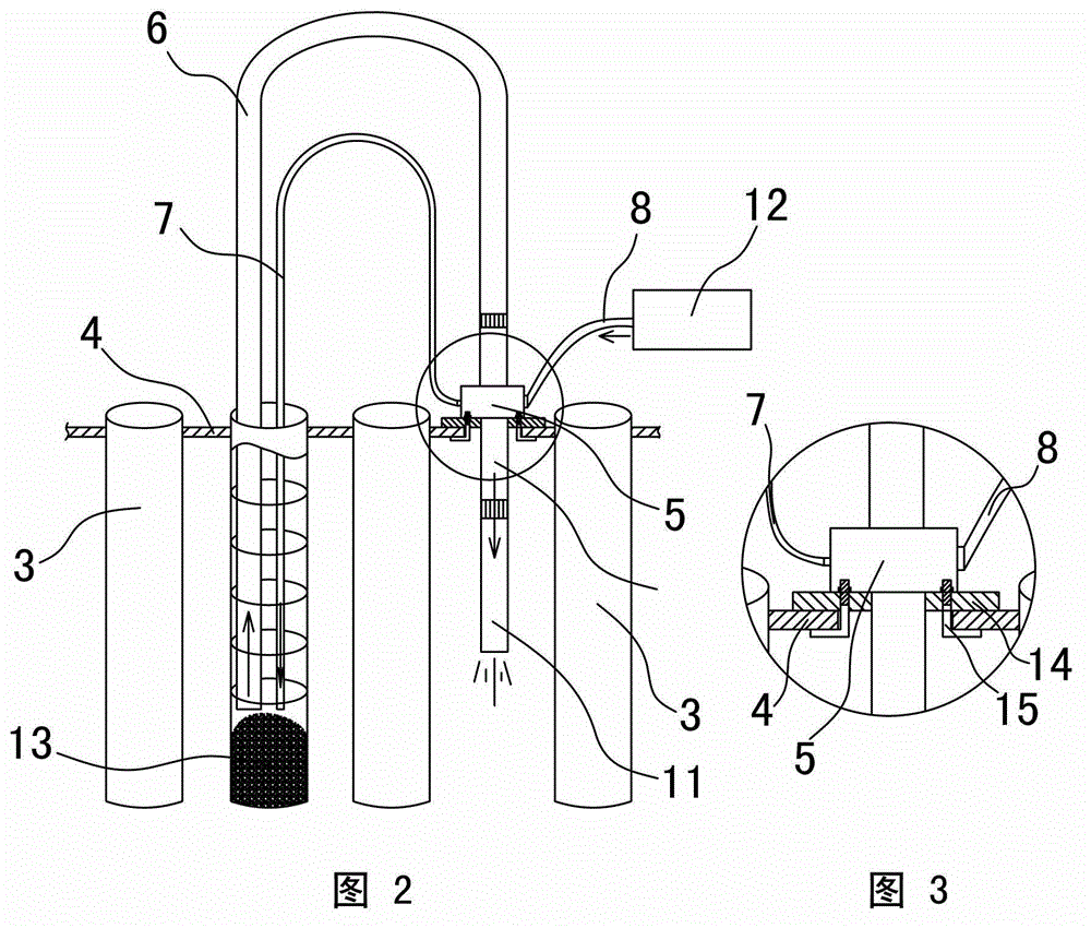
[0030] See attached figure 2 , attached image 3 , attached Figure 4 And attached Figure 5 As shown, a gas distributor 5 is included, an exhaust port 10 and a suction port 9 are provided on the gas distributor 5, and a gas flow connecting the exhaust port 10 and the suction port 9 is provided in the gas distributor 5 channel, an annular air chamber 21 is provided on the outside of the air flow channel along the circumference of the air flow direction, and an annular partition wall 27 is used to separate the annular air chamber 21 and the air flow channel. 11 is threadedly connected, and the suction port 9 is threadedly connected with a dust suction pipe 6. The air inlet pipe 8 is provided with an air inlet valve 18, and the air blow pipe 7 is provided with an air blowing valve 19.

[0031] The air flow passage is composed of a flow equalizing section 25 and a flow converging section 20 along the air flow direction, the f...


PUM


Abstract

A fluidized vacuum ash collector comprises a gas distributor; an exhaust vent and an admission port are provided on the gas distributor; an airflow channel that communicates with the exhaust vent and the admission port is provided inside the gas distributor; an annular air chamber along the circumference of the airflow outside the airflow channel is provided; the annular air chamber and the airflow channel are separated by an annular bulkhead; the exhaust vent is connected with an ash discharge pipe and the admission port is connected with an ash suction pipe; the airflow channel comprises current-sharing sections and current-gathering sections in the direction of airflow; an air inlet and an air outlet corresponding to the annular air chamber are provided on the gas distributor; the air inlet communicates with a compressed air source through one admission pipe, and the air outlet communicates with an air blowpipe; jet orifices are provided on the annular bulkhead, which communicate the annular air chamber with the current-gathering section; the angle between the direction of jet orifices and the airflow in the airflow channel is acute angle. The fluidized vacuum ash collector provided by the invention increases the efficiency of ash suction greatly.

Description

technical field [0001] The invention relates to the technical field of dust removal for bag type dust collectors, in particular to a dust suction device for cleaning dust inside filter bags of dust collectors. Background technique [0002] Dust collector is a device that separates dust from flue gas, and is widely used in gas dust removal in foundry, thermal power generation, waste incineration, mining and other industries. At present, most of the dust collectors on the market are bag dust collectors, see the attached figure 1 As shown, the flue gas containing dust and dust enters the dust collector from the flue gas inlet 1. There is a flower plate 4 to prevent the leakage of the flue gas in the dust collector. There are multiple filter bags 3 hanging on the flower plate 4. The material is natural Fiber, chemical synthetic fiber, glass fiber or metal fiber, etc. There is also a cage supporting the filter bag 3 inside the filter bag 3. The flue gas in the dust collector is ...

Claims


Application Information

Patent Timeline
Patent Type & Authority Patents(China)
IPC IPC(8): B01D46/04B01D46/42
Inventor 吴建华
Owner 苏州菲泰科过滤技术有限公司
Why Eureka
Eureka Blog
Learn More