
MWT solar battery and manufacturing method thereof

A technology for solar cells and substrates, applied in circuits, electrical components, and final product manufacturing, etc., can solve the problems of complex process flow, high cost of removing the back field, and achieve the effect of simple process, cost control, and cost saving.

Inactive Publication Date: 2013-08-21
YINGLI GRP
View PDF7 Cites 8 Cited by
  • Summary
  • Abstract
  • Description
  • Claims
  • Application Information

AI Technical Summary

Problems solved by technology

[0005] The present invention aims to provide a MWT solar cell and a preparation method thereof, so as to solve the problems in the prior art that the process flow for removing the back field of the MWT solar cell is complicated and the cost of removing the back field is high

Method used


Image

  • MWT solar battery and manufacturing method thereof

Examples

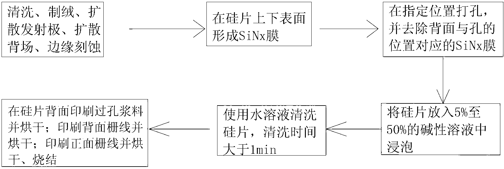

Embodiment Construction

[0019] Hereinafter, the present invention will be described in detail with reference to the drawings and examples. It should be noted that, in the case of no conflict, the embodiments in the present application and the features in the embodiments can be combined with each other.

[0020] Explanation of terms:

[0021] MWT: Metal Emitter Wrap Through Hole Technology.

[0022] Double-sided power generation battery: The front and back of the battery are designed with main grid and fine grid, so that the back of the battery can also absorb light and improve the utilization rate of light.

[0023] Back field (diffusion back field): On the back side of the silicon wafer (the side where the pn junction is not formed), a high-low junction is formed through diffusion, that is, the back field.

[0024] Strong alkaline solution: an alkaline solution that can completely ionize in water and release hydroxide ions.

[0025] Such as figure 1 As shown, according to an embodiment of the pr...


PUM


Abstract

The invention provides an MWT solar battery and a manufacturing method of the MWT solar battery. The manufacturing method of the MWT solar battery comprises the following steps that antireflection films in a designated area on the back face of a substrate of the MWT solar battery are removed through laser to form an non-antireflection film area; the substrate of the MWT solar battery is placed into a strong alkaline solution to be cleaned, and the back field of the non-antireflection film area, laser damage and material passing hole interior damage are removed. In the manufacturing method of the MWT solar battery, the antireflection films which are needed in MWT solar battery production are used as masks, therefore other masks do not need to be manufactured additionally, and extra processes, equipment and materials do not need to be added. Compared with the prior art, the MWT solar battery is high in process integration degree, simple in process and beneficial to cost controlling.

Description

technical field [0001] The invention relates to the field of solar cell manufacturing, in particular to a MWT solar cell and a preparation method thereof. Background technique [0002] In the process of preparing MWT solar cells with a back field, it is necessary to lead the front grid lines to the back through the via hole paste, and form a paste point with a diameter of 2 to 5 mm on the back to facilitate the formation of components. The high temperature during laser drilling will form a damaged layer on the hole wall and the laser incident surface, and the carrier recombination center in the damaged layer will reduce the life of photogenerated carriers and cause battery leakage; the front grid line and the back grid line of the feed hole need Insulation treatment, due to the existence of the back diffusion field, the place where the via paste point contacts the silicon wafer will cause leakage. Therefore, it is necessary to remove the damaged layer caused by drilling and...

Claims


Application Information

Patent Timeline
Patent Type & Authority Applications(China)
IPC IPC(8): H01L31/18H01L31/0216
CPCY02P70/50
Inventor 陈迎乐赵文超王建明王子谦李高非胡志岩熊景峰
Owner YINGLI GRP
Learn More