
burners for gas hobs

A technology for burners and gas stoves, which is applied in the direction of gas fuel burners, burners, and combustion methods. It can solve the problems of short mixing time and mixing path, unfavorable full combustion of gas, and insufficient combustion of yellow flames, so as to avoid burning Insufficient, long mixing time, the effect of improving the mixing effect

Active Publication Date: 2015-10-28
GUANGDONG VANWARD ELECTRIC
View PDF6 Cites 0 Cited by
  • Summary
  • Abstract
  • Description
  • Claims
  • Application Information

AI Technical Summary

Problems solved by technology

[0002] In the prior art, the primary air volume of the gas stove usually comes from under the panel. The air and gas entering the burner are not easy to mix evenly due to the short mixing time and mixing channel, which is not conducive to the full combustion of the gas, resulting in the existence of a gas stove. Due to the short mixing time and mixing path of the burner, it is easy to produce insufficient combustion defects such as yellow flames

Method used


Image

  • burners for gas hobs
  • burners for gas hobs
  • burners for gas hobs

Examples


specific Embodiment approach

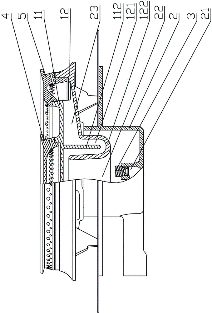
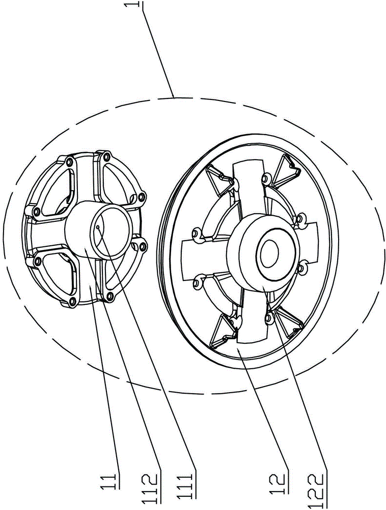
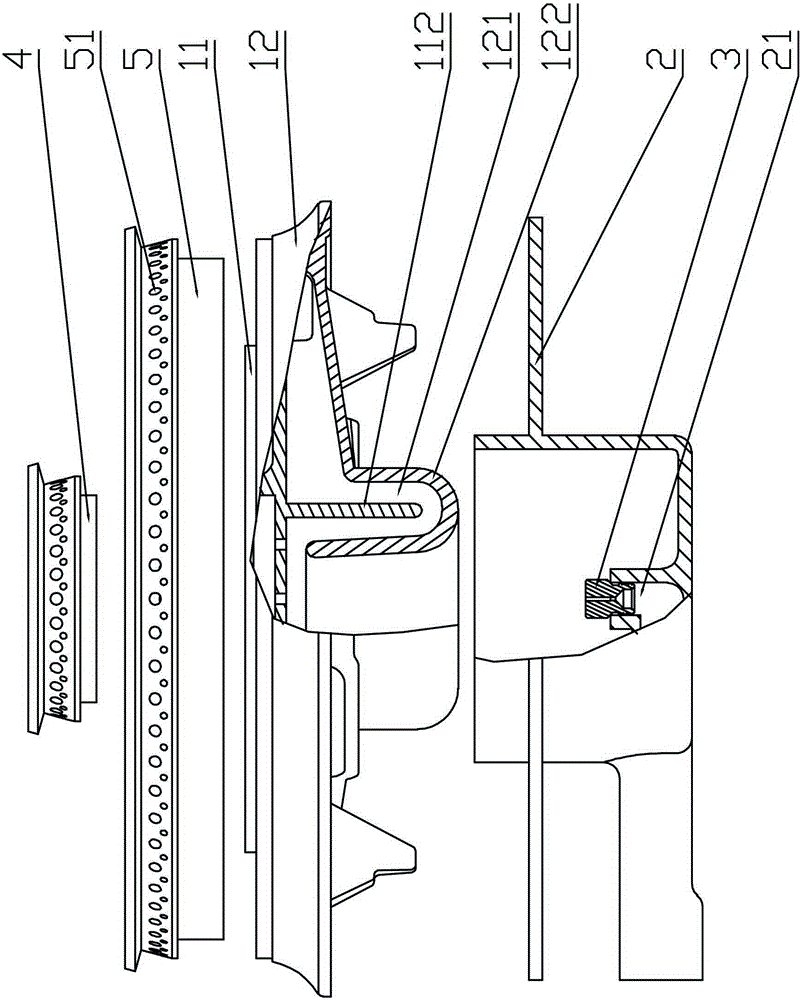
[0023] Specific implementation method: see attached figure 1 , attached figure 2 , attached image 3 , attached Figure 4 , attached Figure 5 , attached Figure 6 , attached Figure 7 As shown, the present embodiment includes an upper seat 1, a lower seat 2, a nozzle 3, a central fire distribution device 4, and an outer ring fire distribution device 5. The injection cavity 22 and the mixing cavity 23, the injection cavity 22 is located above the nozzle 3, the upper seat 1 includes the upper seat top plate 11 and the upper seat bottom plate 12, the upper seat top plate 11 and the upper seat bottom plate 12 can be connected by riveting or screw connection to form a complete upper seat 1 . as attached Figure 4 As shown, the upper seat top plate 11 is covered on the upper seat bottom plate 12 to form a "U" type mixing channel 121, as attached Figure 5 As shown, the upper seat top plate 11 covers the upper seat bottom plate 12 to form a "W"-shaped mixing channel 121, an...


PUM


Abstract

Disclosed is a burner used for a gas stove. The burner used for the gas stove comprises an upper base, a lower base, a nozzle, a central distributor and an outer ring distributor. The nozzle is installed on a gas outlet of the lower base; the upper base covers the lower base to form an ejecting guiding cavity and a mixing cavity, and comprises an upper base top plate and an upper base bottom plate. The burner used for the gas stove is mainly characterized in that the upper base top plate covers the upper base bottom plate to form a U-type mixing channel or a W-type mixing channel; the ejecting guiding cavity is communicated with the mixing cavity through the U-type mixing channel or the W-type mixing channel. The burner used for the gas stove has the advantages of being capable of prolonging mixing time of air and gas and increasing the length of a mixing path, and accordingly avoiding incomplete combustion phenomena such as yellow flames.

Description

technical field [0001] The invention relates to a burner for a gas stove. Background technique [0002] In the prior art, the primary air volume of the gas stove usually comes from under the panel. The air and gas entering the burner are not easy to mix evenly due to the short mixing time and mixing channel, which is not conducive to the full combustion of the gas, resulting in the existence of a gas stove. Due to the short mixing time and mixing path of advanced burners, it is easy to produce defects such as yellow flames and insufficient combustion. To overcome these drawbacks, burners for gas ranges have been improved. Contents of the invention [0003] The technical problem to be solved by the present invention is to provide a burner for a gas stove, which can effectively prolong the mixing time and mixing path of air and gas, thereby avoiding insufficient combustion such as yellow flames. [0004] The technical solution adopted by the present invention to solve its ...

Claims


Application Information

Patent Timeline
Patent Type & Authority Patents(China)
IPC IPC(8): F23D14/04F23D14/64
Inventor 叶远璋黎有为
Owner GUANGDONG VANWARD ELECTRIC
Learn More