A full counterflow mass flow unit and a tray equipped with the unit

A countercurrent, tray technology, applied in the field of chemical engineering, can solve the problems of low utilization rate of the column section and the pressure drop of the tray, and achieve the effect of increasing the effective mass transfer area, widening the gas phase load range, and improving the utilization rate of the tray.

Active Publication Date: 2014-10-29
HEBEI UNIV OF TECH
View PDF1 Cites 0 Cited by
  • Summary
  • Abstract
  • Description
  • Claims
  • Application Information

AI Technical Summary

Problems solved by technology

[0003] The purpose of the present invention is to provide a full countercurrent gas-liquid mass transfer tower equipment, which can overcome the shortcomings of the low utilization rate of the tower section in the prior art, realize the full countercurrent flow of the gas-liquid two-phase in the tower, and have the ability to process With the advantages of large capacity, high efficiency, large operating flexibility, and plate pressure drop, it can well meet the process requirements of gas-liquid mass transfer tower equipment

Method used


Image

  • A full counterflow mass flow unit and a tray equipped with the unit
  • A full counterflow mass flow unit and a tray equipped with the unit
  • A full counterflow mass flow unit and a tray equipped with the unit

Examples


Embodiment 1-1

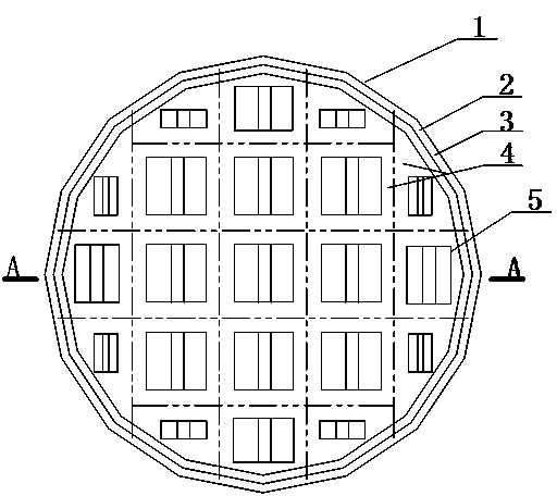
[0023] In the φ650 experimental column, the experiment is carried out by using the full counterflow mass flow tray provided by the present invention. The parameters of the tray structure are as follows:

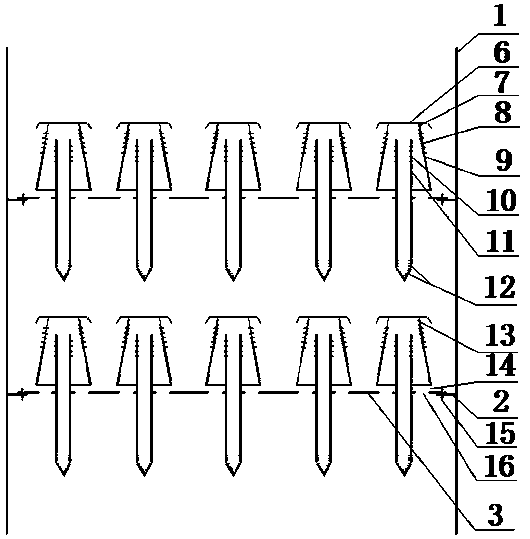
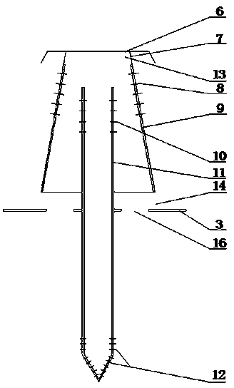
[0024] There is no downcomer, and there are 4 mass transfer unit areas. The mass transfer unit in each mass transfer unit area is 158mm×158mm in size, the plate spacing is 450mm, and the weir height is 50mm. figure 1 As shown, the schematic diagram of the cross-sectional structure of the tray is shown in figure 2 As shown, the schematic diagram of the cross-sectional structure of the mass transfer unit is shown in image 3 shown.

Embodiment 1-2

[0026] Compared with Example 1, the end plate is extended to the gas-liquid separation liquid distribution plate, the injection channel is closed, and the opening ratio of the injection hole of the side plate is correspondingly increased, so that the cross-sectional area of ​​the injection hole of the side plate accounts for the outer surface area of ​​the mass transfer unit The ratio of is the same as the ratio of the sum of the cross-sectional areas of the side plate injection holes and injection channels to the external surface area of ​​the mass transfer unit in Example 1-1. Other structures are the same as in Example 1-1.


PUM


Abstract

The invention discloses a full-countercurrent mass transfer unit and a tower plate with the unit. The mass transfer unit is of a hood-shaped structure with a jet duct. The bottom of the hood-shaped structure is characterized in that the top of the mass transfer unit is closed by a gas-liquid separation liquid-distributing plate (6), a mass transfer liquid-distributing machine (11) is arranged in the mass transfer unit, the lower end of the mass transfer liquid-distributing machine (11) is capable of penetrating the tower plate, the upper end of the mass transfer liquid-distributing machine (11) extends into the mass transfer unit, the upper end of the mass transfer liquid-distributing machine (11) is provided with an upper jet hole (10), and the lower end of the mass transfer liquid-distributing machine (11) is provided with a lower jet hole (12).

Description

technical field [0001] The invention relates to a gas-liquid mass transfer device in the field of chemical engineering, in particular to a tower device in which gas-liquid flows countercurrently in the device and transfers mass and heat in a high-speed spray state. Background technique [0002] Tower equipment is an important gas-liquid mass transfer equipment in chemical production, and its internal structure is mainly composed of support rings, downcomers and trays. The support ring plays the role of supporting the tray, the downcomer is the channel for the liquid to flow, and the tray is the original part of the gas-liquid contact, and the gas-liquid two-phase cross-flow flows on the tray. Generally, the downcomer should occupy about 10% of the cross-sectional area of ​​the tower, and then remove the area that cannot be opened, such as the liquid receiving plate, sides, corners, etc., and the gas-liquid mass transfer components (such as bubble caps, float valves, etc.) ca...

Claims


Application Information

Patent Timeline
Patent Type & Authority Patents(China)
IPC IPC(8): B01J19/32
Inventor 刘继东吕建华
Owner HEBEI UNIV OF TECH
Why Eureka
Try Eureka