Eureka AIR delivers breakthrough ideas for toughest innovation challenges, trusted by R&D personnel around the world.

Simple mousetrap

A mousetrap, simple technique

Inactive Publication Date: 2013-08-21
彭云召
View PDF7 Cites 0 Cited by
  • Summary
  • Abstract
  • Description
  • Claims
  • Application Information

AI Technical Summary

Problems solved by technology

[0002] Various mousetraps currently on the market have problems such as complex structure, high cost, and inconvenient operation.

Method used


Image

  • Simple mousetrap
  • Simple mousetrap
  • Simple mousetrap

Examples


specific Embodiment approach

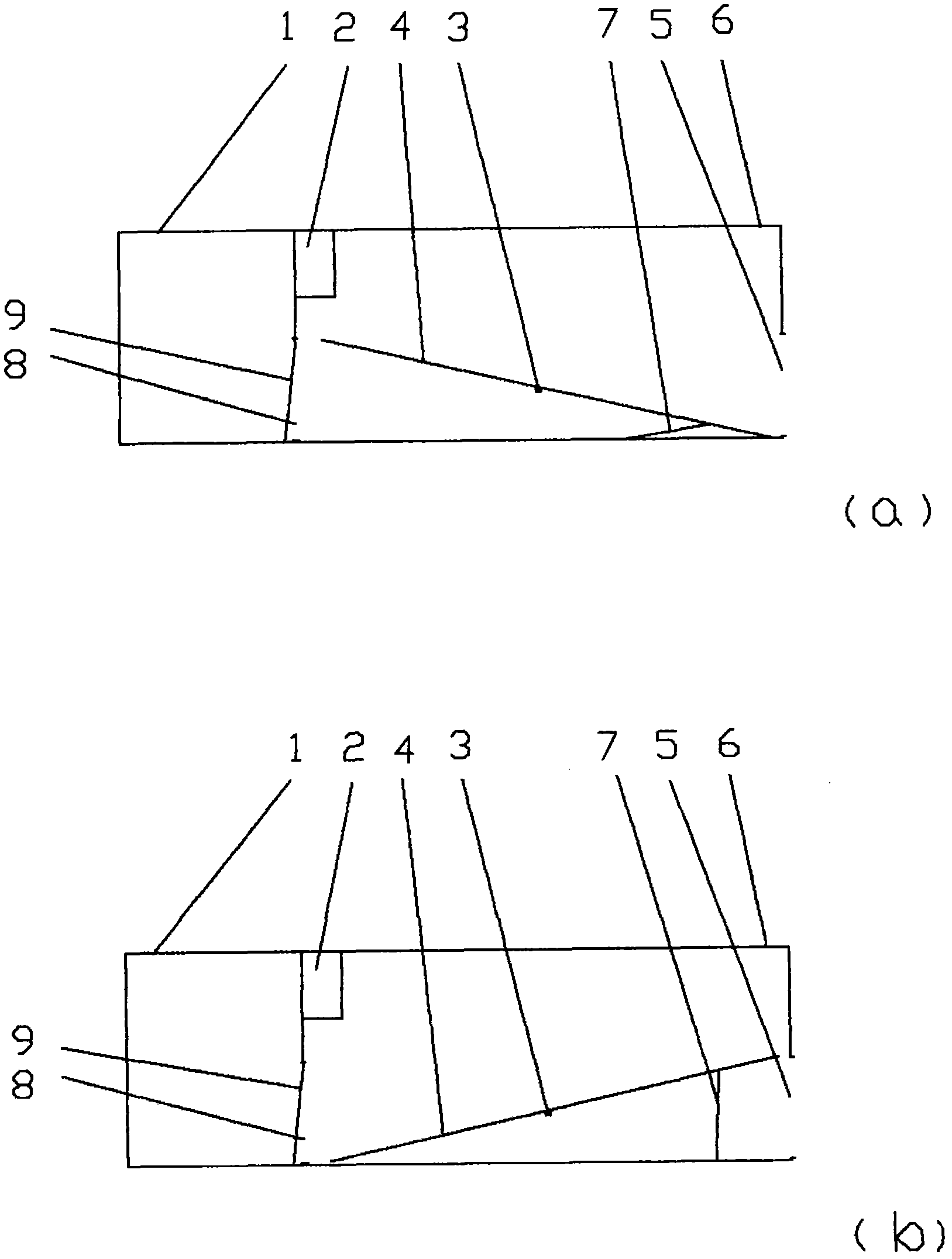
[0011] Specific implementation method: in figure 2 In (a) and (b), the mouse trap box is connected with a seesaw horizontal axis 3, the seesaw plate horizontal axis 3 is connected with a seesaw plate 4, the seesaw plate 4 is connected with a control rod 7, and the mouse trap box 4 is connected with There are 1 mouse silos.

[0012] When needing to catch mice, earlier the mousetrap is placed on the place where mice appear, a small amount of bait is placed in the bait box 2 of the mousetrap box, and the lower end of the control rod 7 is pushed in from the mouse entrance 5 with fingers to make the seesaw 4 Fall down automatically, form a channel with the mouse trap entrance 5. When the mouse enters the mouse trap 6 and walks to the other end of the seesaw 4, the seesaw 4 falls, and the outer end of the seesaw 4 rises thereupon, and the control rod 7 stands up under the drive of the seesaw 4, Hold the seesaw 4 so that it cannot fall. At this moment, the mouse in the mousetrap ...


PUM


Abstract

The invention discloses a simple mousetrap which mainly comprises a trap box, a see-saw board transverse shaft, a see-saw board, a control rod and a mouse chamber. The simple mousetrap is characterized in that the see-saw board transverse shaft is connected inside the trap box and is connected with the see-saw board, the see-saw board is connected with the control rod, and the mouse chamber is connected to the trap box. The simple mousetrap is simple in structure, convenient to operate and effective in trapping.

Description

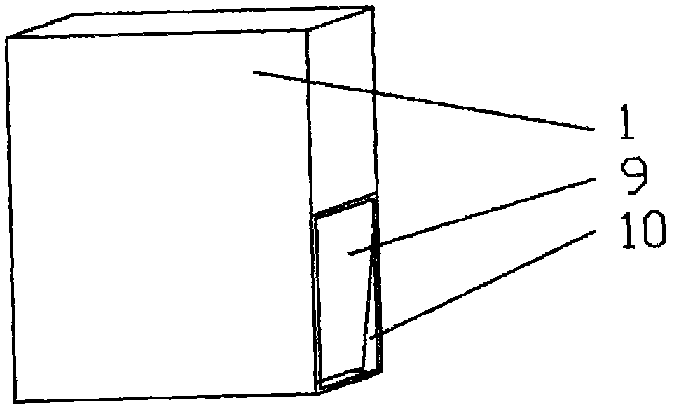
Technical field: [0001] The invention relates to a mousetrap, which is a simple mousetrap. Background technique: [0002] The various mousetraps sold in the market have problems such as complex structure, high cost, and inconvenient operation. Invention content: [0003] In order to overcome the above existing deficiencies, the object of the present invention is to provide a simple mousetrap, which uses a seesaw and a control rod to cooperate to catch mice. [0004] The object of the present invention is achieved in that the mousetrap comprises: a mousetrap box, a seesaw horizontal axis, a seesaw, a control rod and a mouse bin. It is characterized in that: the mouse trap is connected with a seesaw horizontal axis; [0005] The beneficial effect is that the mousetrap has simple structure, convenient operation and good mouse-catching effect. Description of drawings: [0006] figure 1 It is the overall picture of the simple mousetrap; [0007] figure 2 (a) is the int...

Claims


Application Information

Patent Timeline
Patent Type & Authority Applications(China)
IPC IPC(8): A01M23/04
Inventor 彭云召
Owner 彭云召
Why Eureka
Eureka Blog
Learn More