
A distance measuring method and system based on binocular stereo vision

A technology of binocular stereo vision and distance measurement method, which is applied in the field of distance measurement and can solve the problems of complex operation and long time consumption

Inactive Publication Date: 2015-11-11
NANJING UNIV OF AERONAUTICS & ASTRONAUTICS
View PDF6 Cites 0 Cited by
  • Summary
  • Abstract
  • Description
  • Claims
  • Application Information

AI Technical Summary

Problems solved by technology

However, most accurate calibration algorithms require additional calibration templates, which are complicated to operate and take a long time. In addition, once any parameters of the camera system change, they need to be re-calibrated, which is only suitable for places where the camera is fixed.

Method used


Image

  • A distance measuring method and system based on binocular stereo vision
  • A distance measuring method and system based on binocular stereo vision
  • A distance measuring method and system based on binocular stereo vision

Examples


Embodiment

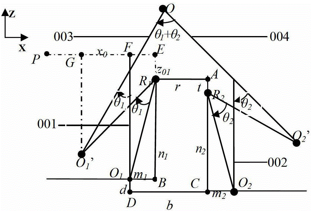
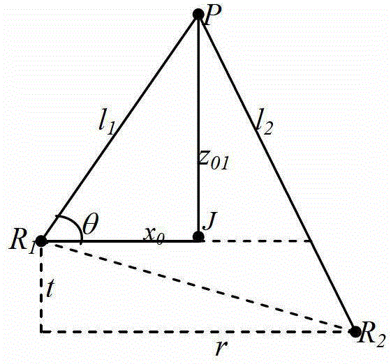
[0108] Using a thermal imager and a CCD camera to conduct ranging experiments on two target points A and B at different distances at different angles, the thermal imager used in the experiment is a vanadium oxide uncooled focal plane detector. The results are shown in Table 1. In this scene r=155mm, t=-120mm.

[0109] Table 1 The result of the ranging method of the present invention

[0110]

[0111] Note: Relative error calculation formula:

[0112] E. l =︱l 1t -l 1c ︱ / l 1t ×100%

[0113] E. θ =︱θ t -θ c ︱ / |θ t |×100%

[0114] where l 1t , θ t Indicates the real distance and direction angle of the target, l 1c , θ c is the target distance and direction angle calculated according to the method in this paper, and ︱︱ represents the absolute value.


PUM


Abstract

The invention discloses a distance measurement method and system based on binocular stereo vision. The method comprises the following steps: acquiring a position relationship between two fixed points; constructing a distance measurement model by using one fixed point as the original point according to the position relationship; and acquiring unknown parameters through easy calibration according to the model so as to realize the distance measurement of a target. The method can enlarge the information amount of infrared-visible images and provide position information of the target by using a heterogeneous source consisting of a thermal imager and a visible CCD (charge coupled device) camera to measure the distance.

Description

technical field [0001] The invention relates to a distance measuring method, more specifically a distance measuring method and system based on binocular stereo vision. Background technique [0002] The binocular stereo vision distance measurement method is a passive distance measurement method, which imitates a distance measurement method that humans use binocular perception of distance. It mainly uses two cameras to image the same object at different positions in the public field of view to obtain stereoscopic comparison, and measures the distance information of the object according to the imaging parallax. Existing binocular stereo vision ranging systems are all realized by a single-source visible light image sensor. However, when encountering severe weather with low visibility such as heavy fog and rain, or other complex environments, it is difficult to achieve target ranging by only relying on a pair of visible light cameras. With the rapid development of science and t...

Claims


Application Information

Patent Timeline
Patent Type & Authority Patents(China)
IPC IPC(8): G01C3/14
Inventor 曹力陈文
Owner NANJING UNIV OF AERONAUTICS & ASTRONAUTICS
Learn More