
Check valve

A check valve and check sheet technology, applied in the field of residential shared exhaust systems, can solve the problems of increasing materials, labor costs, deviations in production and installation, affecting the sealing effect, etc., saving materials and labor costs, and increasing overall strength. , a strong overall effect

Inactive Publication Date: 2013-08-14
张琦
View PDF8 Cites 2 Cited by
  • Summary
  • Abstract
  • Description
  • Claims
  • Application Information

AI Technical Summary

Problems solved by technology

[0002] At present, the existing check valve of this type has the problem of deviation in the process of production and installation, which affects the sealing effect, and increases the cost of materials and labor, and the integrity is not strong

Method used


Image

  • Check valve
  • Check valve
  • Check valve

Examples


no. 1 example

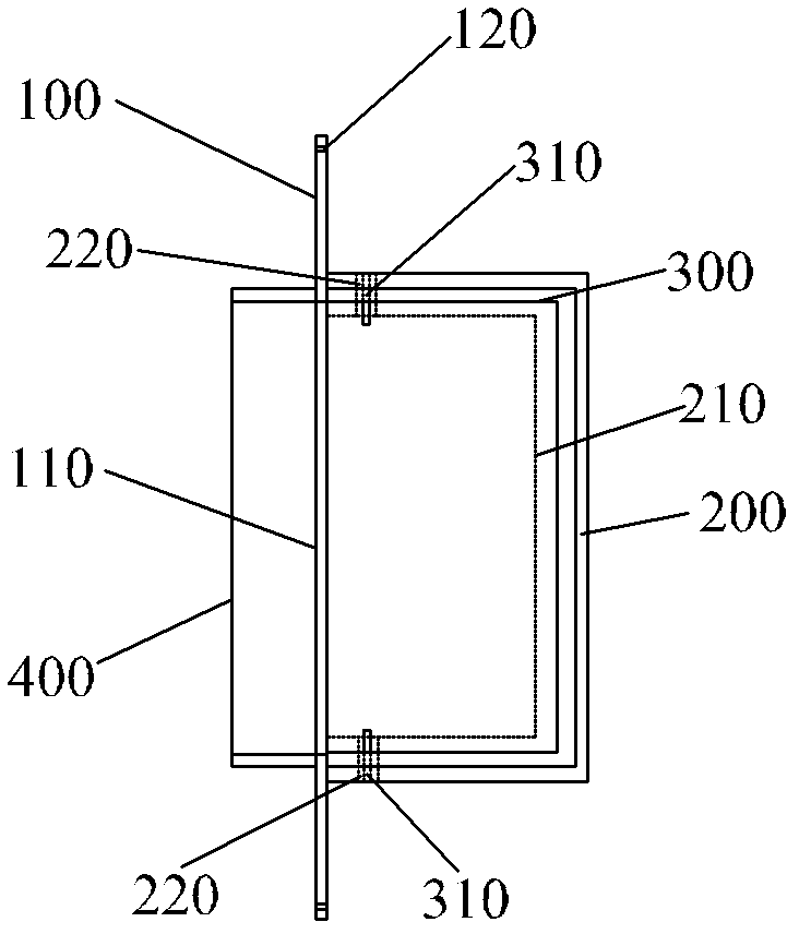
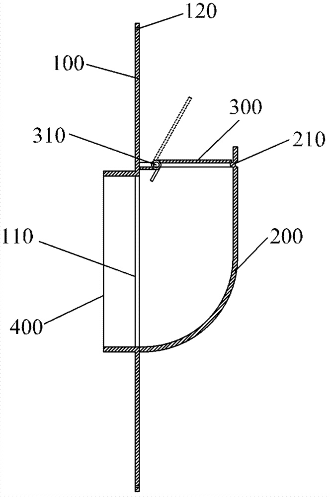
[0016] refer to figure 1 ,, figure 2 , is a schematic diagram of the structure of the check valve in the first embodiment of the present invention. The check valve in this embodiment is located at the air inlet of the residential common exhaust system. The check valve includes a panel 100 provided with an air inlet 110, a guide pipe 200 arranged inside the panel 100 and communicating with the air inlet 110, and a normally closed valve which is arranged on the guide pipe 200 and can cover the outlet 210 of the guide pipe. Check sheet 300. At least two side walls of the guide tube 200 are provided with a first inner convex outer concave belt 210 , and the normally closed non-return piece 300 is superimposed and closed with the first inner convex outer concave belt 210 . in, figure 2 The middle dotted line shows the state when the normally closed non-return piece 300 is opened. The first inner convex outer concave belt 210 of the check valve in the present invention is sta...

no. 2 example

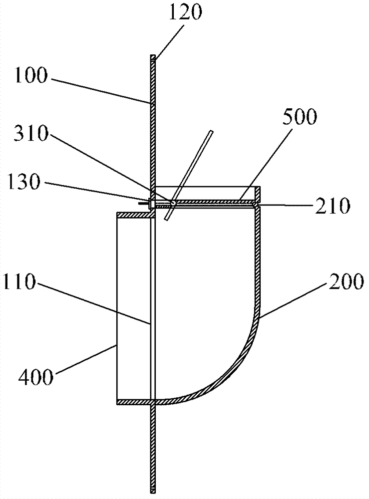
[0025] refer to image 3 , is a schematic cross-sectional view of the second embodiment of the check valve provided by the present invention. The difference between this embodiment and the first embodiment is that the panel 100 is provided with an opening 130 , and the guide tube 200 is provided with a normally closed non-return device 500 which can be pulled out from the opening 130 and inserted. The normally closed non-return device 500 cooperates with the first inner convex outer concave belt 210 of the guide pipe 200 to position and slide, and is pulled out or inserted from the opening 130 of the panel 100, thus facilitating the cleaning and replacement of the normally closed non-return device 500. The normally closed check device 500 can be made of plastic or metal. image 3 The middle dotted line shows the state when the non-return piece of the normally closed non-return device 500 is opened. Other structures of the check valve in this embodiment are the same as those ...


PUM


Abstract

The invention relates to the technical field of common exhaust systems of houses and provides a check valve. The check valve is provided with a panel, a guide tube and a normally-closed check sheet. The panel is provided with an air inlet, the guide tube is arranged on one side of the panel and communicated with the air inlet, and the normally-closed check sheet is arranged in the guide tube, a first inner-protruding and outer-concave strip is arranged on the wall of the guide tube, and the normally-closed check sheet is stacked and sealed with the first inner-protruding and outer-concave strip. The first inner-protruding and outer-concave strip is punched and molded through the guide tube wall, so that the wholeness is high, the manufacture is simple and accurate, and materials and labor costs are saved; and the first inward-protruding and outward-concave strip have a function of a reinforcing rib, so that the whole strength of the check valve is increased. The normally-closed check sheet is opened when air is exhausted towards an exhaust passage system and falls back automatically to be sealed with the first inner-protruding and outer-concave strip when exhausting towards the exhaust passage system is stopped, so that backward flowing of the exhaust passage system is prevented.

Description

technical field [0001] The invention relates to the technical field of residential shared exhaust systems, and more specifically relates to a check valve installed at the air inlet of a shared exhaust duct system. Background technique [0002] At present, the existing check valve of this type has the problem of deviation in the process of manufacture and installation, which affects the sealing effect, and increases material and labor costs, and the integrity is not strong. Contents of the invention [0003] The technical problem to be solved by the present invention is to overcome the defects of the prior art, and provide a check valve that saves labor and materials, is simple and precise to manufacture, and has enhanced overall strength. [0004] In order to solve the above-mentioned technical problems, the present invention provides a check valve, which includes a panel with an air inlet, a guide pipe arranged on one side of the panel and communicated with the air inlet,...

Claims


Application Information

Patent Timeline
IPC IPC(8): F16K15/03
Inventor 张琦
Owner 张琦
Learn More