Separating ring of high-gradient magnetic separator

A high-gradient magnetic separator and magnetic separator technology, applied in the field of machinery, can solve problems such as difficulty in unloading medium concentrate, insufficient separation space, and affecting equipment processing capacity, etc., and achieve simple and reliable structure, low cost, and increased productivity. The effect of large sorting space

Inactive Publication Date: 2013-08-14
GUANGZHOU RES INST OF NON FERROUS METALS +1
View PDF8 Cites 6 Cited by
  • Summary
  • Abstract
  • Description
  • Claims
  • Application Information

AI Technical Summary

Problems solved by technology

However, the sorting space of this magnetic separator is not large enough, mainly due to the limitation of the pole distance of the magnetic field and the thickness of the medium.
Because the pole distance is too large, the background field strength of the sorting space will decrease, or it can be solved by increasing the number of ampere turns of the coil, but this needs to greatly increase power consumption, and increasing the thickness of the medium will make it difficult to unload the concentrate
If the sorting space is not large, it is impossible to load a larger volume of media, which affects the processing capacity of the equipment. Especially when the equipment needs to be enlarged, the contradiction between the increase of the thickness and volume of the media and the clogging phenomenon becomes more prominent.

Method used


Image

  • Separating ring of high-gradient magnetic separator
  • Separating ring of high-gradient magnetic separator
  • Separating ring of high-gradient magnetic separator

Examples


Embodiment Construction

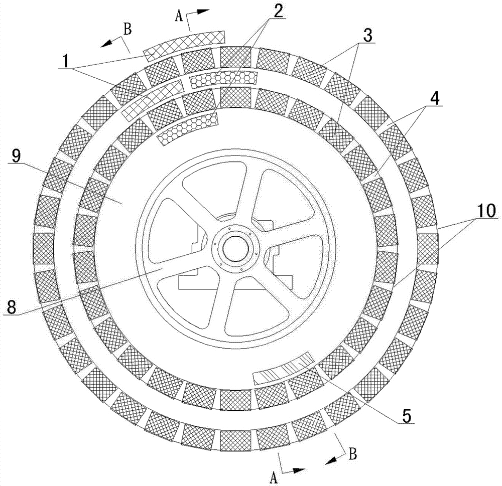
[0020] Such as Figure 1-Figure 6 As shown, the separation ring of the high-gradient magnetic separator of the present invention includes a ring body 9 that is installed on the turntable 8 of the magnetic separator and can rotate synchronously with the turntable and at least two rings that are installed on the periphery of the ring body 9. Layers are used to accommodate and fix the arc groove 10 of the medium box 3, the medium box 3, the ore unloading device 1 installed on the outer periphery of each arc groove 10, the ore receiving device 2 respectively installed on the inner periphery of each arc groove 10, and the The ore feeder 5 in the annulus 9. Wherein, the above-mentioned medium boxes 3 are welded by magnetically conductive stainless steel rods (medium) according to certain rules, and a partition 4 is arranged between two adjacent medium boxes 3 . The medium can gather magnetic force lines in the magnetic field, so a magnetic field with a high gradient can be formed a...


PUM


Abstract

The invention relates to a separating ring of a high-gradient magnetic separator. The separating ring comprises a ring body, at least two layers of arc grooves, medium boxes, ore unloaders, ore receivers and an ore feeder, wherein the ring body is arranged on a turntable of the magnetic separator and can rotate along with the turntable; the arc grooves are formed in the periphery of the ring body and used for containing and fixing the medium boxes; the ore unloaders are respectively arrange at the outer circumferences of the arc grooves; the ore receivers are respectively arranged at the inner circumferences of the arc grooves; and the ore feeder is arranged in the ring body. According to the separating ring, by adopting the structure of arranging the at least two layers of medium boxes on the ring body, the thickness of each layer of medium boxes can be greatly reduced; as the number of the layers of medium boxes is increased, a large-volume medium can be mounted in the separating ring, thus effectively enlarging the separating space while ensuring the enough magnetic field intensity, and greatly increasing the processing capacity of the magnetic separator; especially when the magnetic separator equipment needs to be large-scale, the separating ring structure can even effectively ensure that more medium can be conveniently and reliably mounted so as to sufficiently ensure the separating effect; and the structure is simple and reliable, the cost is low and the efficiency is high.

Description

technical field [0001] The invention belongs to the technical field of machinery, and in particular relates to a sorting ring of a high-gradient magnetic separator of an ore concentrator. Background technique [0002] The high-gradient magnetic separation theory has brought a qualitative leap to the field of magnetic separation, increasing the types of minerals that can be magnetically separated, and widening the upper and lower limits of particle size. [0003] Early high-gradient magnetic separators are periodic, also known as magnetic filters, and this type of equipment is widely used in occasions with extremely low magnetic content and very fine particle size. [0004] The continuous high gradient magnetic separators that appeared immediately include electromagnetic flat ring strong magnetic high gradient magnetic separators, permanent magnet and electromagnetic double vertical ring high gradient magnetic separators. Electromagnetic flat-ring high-gradient magnetic sepa...

Claims


Application Information

Patent Timeline
Patent Type & Authority Applications(China)
IPC IPC(8): B03C1/031
Inventor 汤玉和赵明何健全张军李文博许丽敏刘建国王丽娟徐少华
Owner GUANGZHOU RES INST OF NON FERROUS METALS
Why Eureka
Try Eureka