Circular orbit forming mold

A technology for forming molds and circular orbits, which is applied in the direction of manufacturing tools, metal processing equipment, slot needles, etc., and can solve the problems of reduced service life of related mechanisms

Inactive Publication Date: 2013-08-07
句容泰博尔机械制造有限公司
View PDF7 Cites 2 Cited by
  • Summary
  • Abstract
  • Description
  • Claims
  • Application Information

AI Technical Summary

Problems solved by technology

[0002] One or both ends of the concrete transport tank are equipped with a circular track to keep the tank rotating during transportation and ensure the uniformity of the concrete. If the curvature of the circular track does not meet the requirements, it will follow the tank during transportation. The rotation of the rotation jumps, which reduces the life of the relevant mechanism

Method used


Image

  • Circular orbit forming mold

Examples


Embodiment Construction

[0009] The present invention will be further described below in conjunction with the accompanying drawings and specific embodiments.

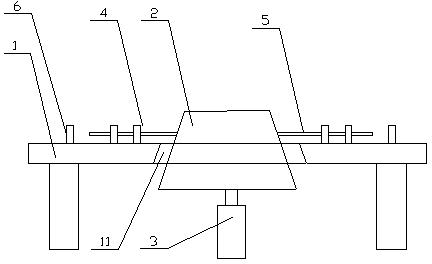
[0010] The circular track molding die includes a platen 1, a truncated cone body 2, a jacking mechanism 3, several guide pieces 4, a pressure column 5 and a limit plate 6, a circular hole 11 is provided in the middle of the platen 1, and the truncated cone body 2 is located on the In the round hole, the jacking mechanism 3 is driven and connected with the frustum of conical body 2, the limit plate 6 is evenly distributed on the side of the platen along a circumferential direction, and the guide piece 4 and the limit plate 6 are correspondingly arranged on a smaller circle, guiding There is a guide hole (not shown in the figure) in the middle of the plate, and the pressure column is slidably arranged in the guide hole, and one end is in contact with the side of the conical frustum body, and the other end is opposite to the limit plate. The jacki...


PUM


Abstract

The invention relates to a circular orbit forming mold which comprises a bedplate, a cone frustum, a lifting mechanism, a plurality of guide pieces, a plurality of pressure columns and a plurality of spacing plates, wherein the middle of the bedplate is provided with a circular hole; the cone frustum is positioned in the circular hole; the lifting mechanism is in drive connection with the cone frustum; the spacing plates are evenly distributed on the upper side surface of the bedplate along a circumferential direction; the guide pieces are arranged on a smaller circumference relative to the spacing plates; the middle of each guide piece is provided with a guide hole; the pressure columns are arranged in the guide holes in a sliding manner; and one end of each pressure column is in contact connection with the side surface of the cone frustum. By using the multiple spacing plates and the multiple pressure columns, the invention ensures that all the parts of a circular orbit are the same in curvature, thereby ensuring that the circular orbit can meet the use requirements in use.

Description

technical field [0001] The invention relates to a circular track molding die. Background technique [0002] One or both ends of the concrete transport tank are equipped with a circular track to keep the tank rotating during transportation and ensure the uniformity of the concrete. If the curvature of the circular track does not meet the requirements, it will follow the tank during transportation. The vibration of the rotation causes the life of the relevant mechanism to be reduced. Contents of the invention [0003] The purpose of the present invention is to solve the above problems, and provides a circular track forming die, which is specifically realized by the following technical features. [0004] A circular track molding die, comprising a platen, a truncated cone body, a jacking mechanism, several guide pieces, a pressure column and a limit plate, a circular hole is arranged in the middle of the platen, and the truncated cone body is located in the circular hole, Th...

Claims


Application Information

Patent Timeline
IPC IPC(8): B21H7/18
Inventor 胡惠球笪远宁周光明
Owner 句容泰博尔机械制造有限公司
Why Eureka
Try Eureka