An electronic synchronization device for an automatic bar feeding machine

A technology of automatic feeding and synchronizing device, applied in metal processing equipment and other directions, can solve the problems of fracture, small clip and material, clip detachment from material, etc.

Inactive Publication Date: 2015-07-29
WUJIANG KEWOKE MACHINERY EQUIP
View PDF5 Cites 0 Cited by
  • Summary
  • Abstract
  • Description
  • Claims
  • Application Information

AI Technical Summary

Problems solved by technology

[0002] When a feeder without a synchronous mechanism is used with a slitting (spindle moving) CNC lathe, because the clamping force between the material clamp and the material is small, when the lathe spindle clamps the material at high speed (the maximum speed can reach 50M / minutes), the feeder’s plunger can’t keep up with such a fast moving speed, so that the clip is separated from the material
In this way, the material itself has been processed, but the feeder does not send a material shortage signal to the lathe, so that the lathe will not stop processing. When the last workpiece is processed, the remaining material remains on the guide sleeve of the lathe. , because the length of the remaining material is too short, the spindle of the lathe cannot be clamped, the remaining material does not rotate with the main shaft, the turning tool still moves according to the original program, and it will break when it hits the material

Method used


Image

  • An electronic synchronization device for an automatic bar feeding machine
  • An electronic synchronization device for an automatic bar feeding machine
  • An electronic synchronization device for an automatic bar feeding machine

Examples


Embodiment Construction

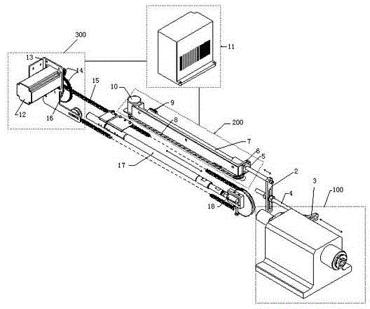
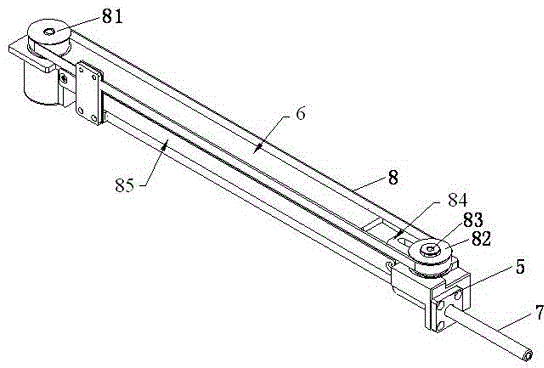
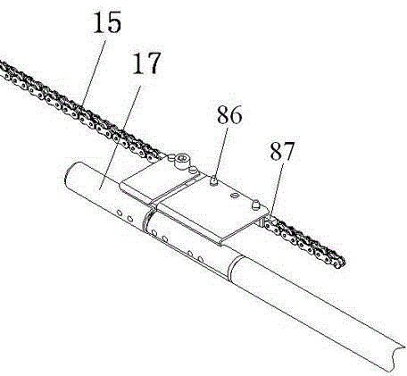
[0008] Such as figure 1 , figure 2 and image 3 As shown, an electronic synchronization device for an automatic bar feeder includes a lathe spindle body, a first synchronization device, and a second synchronization device. The lathe spindle body is connected to the first synchronization device, and the first synchronization device Servo connection with the second synchronous device through a servo amplifier; the first synchronous device includes a base, a linear bearing, a transmission shaft, a first pulley, a second pulley, and a and the timing belt on the periphery of the second pulley, a rotary encoder and a combination seat, the first pulley and the second pulley are installed on the base through the pulley mandrel respectively, and the linear bearing is installed on the end of the base, The transmission shaft is installed in the linear bearing, and also includes a clamping device, the lower part of the clamping device is fixedly connected with one end of the transmissi...


PUM


Abstract

The invention relates to an electronic synchronization mechanism used in combination with a main shaft moveable type lathe. An electronic synchronization device of an automatic bar feeding machine comprises a lathe main shaft body and further comprises a first synchronization device and a second synchronization device, wherein the lathe main shaft body is connected with the first synchronization device; the first synchronization device and the second synchronization device are in servo connection through a servo amplifier; and when a lathe main shaft moves forwards or backwards, a pressing bar and a material clip move forwards and backwards along with lathe main shaft, so that synchronization of the pressing bar, the material clip and the lathe main shaft is realized.

Description

technical field [0001] The invention relates to an electronic synchronous mechanism matched with a movable spindle lathe. Background technique [0002] When a feeder without a synchronous mechanism is used with a slitting (spindle moving) CNC lathe, because the clamping force between the material clamp and the material is small, when the lathe spindle clamps the material at high speed (the maximum speed can reach 50M / minutes), the feeder's plunger can't keep up with such a fast moving speed, so that the material clip is separated from the material. In this way, the material itself has been processed, but the feeder does not send a material shortage signal to the lathe, so that the lathe will not stop processing. When the last workpiece is processed, the remaining material remains on the guide sleeve of the lathe. , because the length of the remaining material is too short, the spindle of the lathe cannot be clamped, and the remaining material does not rotate with the main ...

Claims


Application Information

Patent Timeline
Patent Type & Authority Patents(China)
IPC IPC(8): B23B15/00
Inventor 许任规
Owner WUJIANG KEWOKE MACHINERY EQUIP
Why Eureka
Try Eureka