
Interior article mounting structure for railway vehicle

一种内部设备、铁道车辆的技术,应用在车辆内部照明装置、铁路车辆照明装置、车辆部件等方向,能够解决调节作业费时间等问题,达到安装作业容易进行的效果

Active Publication Date: 2013-07-24
KAWASAKI VEHICLE CO LTD
View PDF6 Cites 6 Cited by
  • Summary
  • Abstract
  • Description
  • Claims
  • Application Information

AI Technical Summary

Problems solved by technology

[0007] However, in the existing vehicle interior equipment, mounting members are required for each interior equipment, and the adjustment must be carried out for each interior equipment.
Therefore, its adjustment work is very time-consuming, and the adjustment must be skilled. Depending on the operator, sometimes the quality of the completion will vary.

Method used


Image

  • Interior article mounting structure for railway vehicle
  • Interior article mounting structure for railway vehicle
  • Interior article mounting structure for railway vehicle

Examples


Deformed example 1

[0083] In the above embodiment, the long holes 5b and 5d for adjusting the position in the vertical direction of the vehicle are formed in the first mounting member 5 (brackets 5A, 5B), but they may be formed in the second mounting member.

Deformed example 2

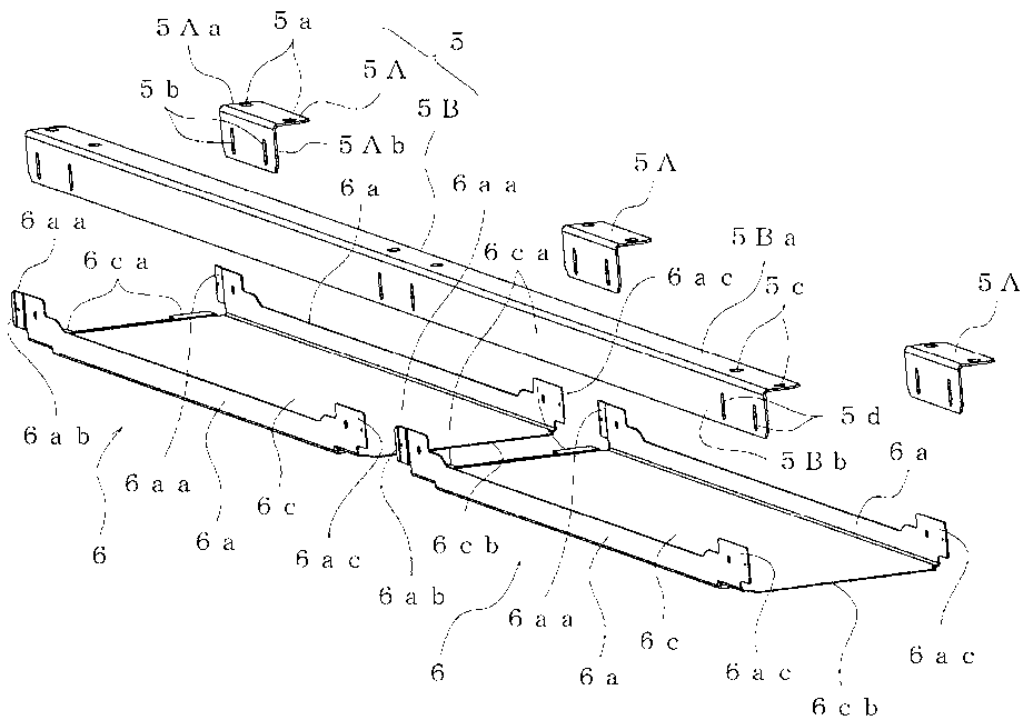
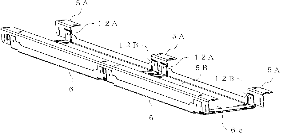
[0085] In the above embodiment, a gap S2 is formed between the flexed extension portion 12Bba of the inner member 12B and the extension portion 6cb of the second attachment member 6 into which the flexion insertion portion 6ca of the adjacent second attachment member 6 is inserted. To form such a gap, only the flexural extension 12Bba or the extension 6cb overlaps the flexion insertion portion 6ca. In addition, when the vehicle interior equipment supported by the second mounting member 6 is light, the inner members 12A and 12B (inner members) may be omitted.

Deformed example 3

[0087] In the above embodiment, the mounting direction of the first mounting member 5 (brackets 5A, 5B) is such that the longitudinal direction of the first mounting member 5 is aligned with the vehicle longitudinal direction, but it may be aligned with the vehicle width direction. For example, such as Figure 8 ~ Figure 9B As shown, the first mounting member 5 (brackets 5A, 5B) is adjusted in position with mechanical fasteners 11F and is mounted on a hanging groove 21a formed on the roof structure 21 and extending in the longitudinal direction of the vehicle so that The length direction of the mounting member is the vehicle width direction. Furthermore, elongated holes 5b and 5d are provided in the first bracket 5A and the second bracket 5B (first mounting member 5), and the first mounting member 5 and the second mounting member 6 are fastened with mechanical fasteners 11G. At this time, since the long holes 5b and 5d are used, the position can be adjusted in the vertical dir...


PUM


Abstract

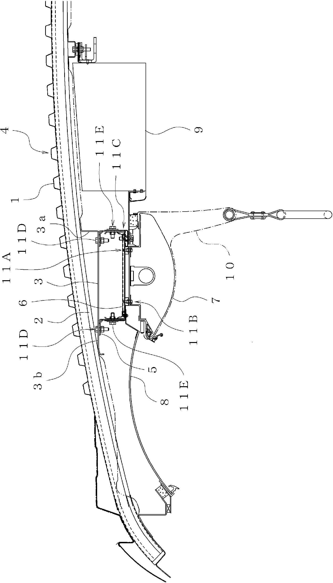
The present interior article mounting structure for a railway vehicle is configured in such a manner that a first mounting member (5) is mounted to a roof structure (4) so as to extend in the longitudinal direction of the vehicle or in the width direction of the vehicle. Second mounting members (6) are mounted to the first mounting member (5) using mechanical fasteners (11E), such as bolts, with the positions of the second mounting members (6) adjusted in the vertical direction of the vehicle. The second mounting members (6) are members for mounting lighting devices (7), such as fluorescent lights, thereto, have a size corresponding to the lighting devices (7), and are mounted continuously. Portions at which plate members overlap each other are present between the second mounting members (6), and receivers (10) for a bar for straps are mounted to the portions.

Description

Technical field [0001] The invention relates to an internal equipment installation structure for installing internal equipment of a vehicle and a railway vehicle. Background technique [0002] Inside the vehicle structure of a railway vehicle, for example, between the roof structure and the cabin, there are installed vehicle interior equipment (roof interior equipment) such as air conditioning equipment, air conditioning ducts, fluorescent lights, booms, and side roofs. [0003] The railway vehicle has a wide indoor space of approximately 3 m in width x approximately 20 m in length in a plan view, and it is required that all the vehicle interior equipment be installed beautifully in order for passengers and the like to look around the vehicle interior equipment in a wide range. In particular, the vehicle interior equipment installed on the roof has a great influence on the aesthetics of passengers. Therefore, when the vehicle interior equipment of the same shape is installed regula...

Claims


Application Information

Patent Timeline
Patent Type & Authority Applications(China)
IPC IPC(8): B61D17/18B60Q3/02B61D17/12B61D29/00B61D37/00E04B9/00F16B5/02
CPCB61D17/12B61D27/00B61D17/00B61D37/00B61D17/18B60Q3/43
Inventor 三谷雄一郎东隆司
Owner KAWASAKI VEHICLE CO LTD
Learn More