
Dynamics modeling method of over-constrained heavy parallel machine tool applied to real-time control

A real-time control and over-constraint technology, applied in the direction of digital control, electrical program control, etc., can solve the problems that the elastic dynamic model cannot be applied to the real-time control system and the rigid body dynamic model has low precision, so as to meet the real-time requirements and computational efficiency High, the effect of improving the accuracy of the model

Active Publication Date: 2013-07-24
TSINGHUA UNIV
View PDF4 Cites 6 Cited by
  • Summary
  • Abstract
  • Description
  • Claims
  • Application Information

AI Technical Summary

Problems solved by technology

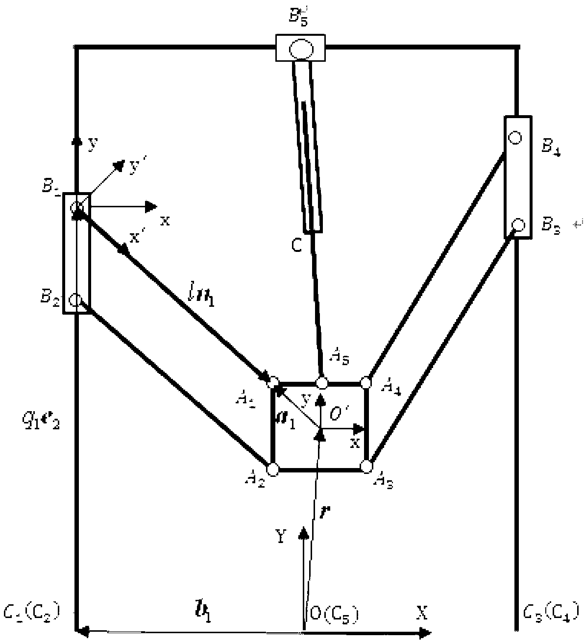
[0005] The purpose of the present invention is to disclose a dynamic modeling method for over-constrained heavy-duty parallel machine tools oriented to real-time control applications, to overcome the defects that the current rigid body dynamic model has low precision and the elastic dynamic model cannot be applied to real-time control systems

Method used


Image

  • Dynamics modeling method of over-constrained heavy parallel machine tool applied to real-time control
  • Dynamics modeling method of over-constrained heavy parallel machine tool applied to real-time control
  • Dynamics modeling method of over-constrained heavy parallel machine tool applied to real-time control

Examples


Embodiment Construction

[0018] The method embodiment of the present invention comprises the following steps as follows:

[0019] 1) According to the structure of the over-constrained heavy-duty parallel machine tool, through the kinematic analysis of the machine tool, the position, velocity and acceleration of each joint of the machine tool are obtained; Establish the velocity relationship between the moving platform of the machine tool and each active joint according to the Jacobian matrix; specifically include:

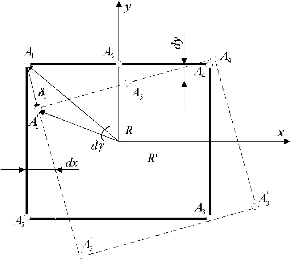
[0020] 11) Establish a fixed coordinate system O-XY fixed on the machine frame, such as figure 1 As shown, point O is the contact point C between the two columns of the machine tool and the ground 1 、C 3 The midpoint of the center point; the X-axis is horizontally to the right, and the Y-axis is vertically upward; the fixed coordinate system O′-xy established on the moving platform, the center position of the moving platform is recorded as O′, the x-axis is horizontally to the right, and...


PUM


Abstract

The invention discloses a dynamics modeling method of an over-constrained heavy parallel machine tool applied to real-time control, and belongs to the technical field of machine tool manufacturing. The method includes confirming positions, speed and accelerated speed of driving joints according to the structure of the machine tool, and confirming positions, speed and accelerated speed of component mass centers; building a speed relation between a movable platform and the driving joints; building force balance equations and torque equations of components of the over-constrained heavy parallel machine tool by means of a Newton-Euler method; according to structure parameters of the over-constrained heavy parallel machine tool and axial deformation situation of rod pieces of a branch chain, building a coordination equation of output errors between deformation and the movable platform; and finally combining the force balance equations, the torque equations and the coordination equation and building a dynamics model. The method takes the deformation of a connecting rod with poor rigidity of the heavy parallel machine tool into consideration and solves the problem that a traditional rigid body dynamics model is low in precision, and the built dynamics model meets real-time calculation requirements of a control system.

Description

technical field [0001] The invention belongs to the technical field of machine tool manufacturing, and in particular relates to a dynamic modeling method of an over-constrained heavy-duty parallel machine tool. Background technique [0002] In theory, parallel machine tools have the advantages of large stiffness-to-mass ratio, fast response speed, and strong environmental adaptability. However, they also have disadvantages such as small working space and many singular configurations. Drive redundancy is an effective way to solve this problem, and drive redundancy can be used for self-calibration of parallel machine tools. In addition, the stiffness of the machine tool can be improved by designing the parallel machine tool as an over-constrained mechanism by introducing an additional link. Therefore, the overconstrained parallel machine tool with drive redundancy has better static and dynamic performance, and is a kind of machine tool with broad application prospects. In or...

Claims


Application Information

Patent Timeline
Patent Type & Authority Applications(China)
IPC IPC(8): G05B19/18
Inventor 吴军王立平李铁民于广阮世松
Owner TSINGHUA UNIV
Learn More