Focusing mechanism of monitoring lens

A lens and support base technology, applied in camera, focusing device, installation, etc., can solve the problems of high manufacturing cost, unsuitable automatic focusing of monitoring lens, complex structure, etc., and achieve convenient focusing, high focusing accuracy, and overall simple structure

Active Publication Date: 2013-07-24
XIAMEN LEADING OPTICS
View PDF10 Cites 9 Cited by
  • Summary
  • Abstract
  • Description
  • Claims
  • Application Information

AI Technical Summary

Problems solved by technology

Although this mechanism can realize the automatic focusing of the camera lens, the structure is relatively complicated, the manufacturing cost is high, and it is not suitable for the automatic focusing of the monitoring lens.

Method used


Image

  • Focusing mechanism of monitoring lens
  • Focusing mechanism of monitoring lens
  • Focusing mechanism of monitoring lens

Examples


Embodiment 1

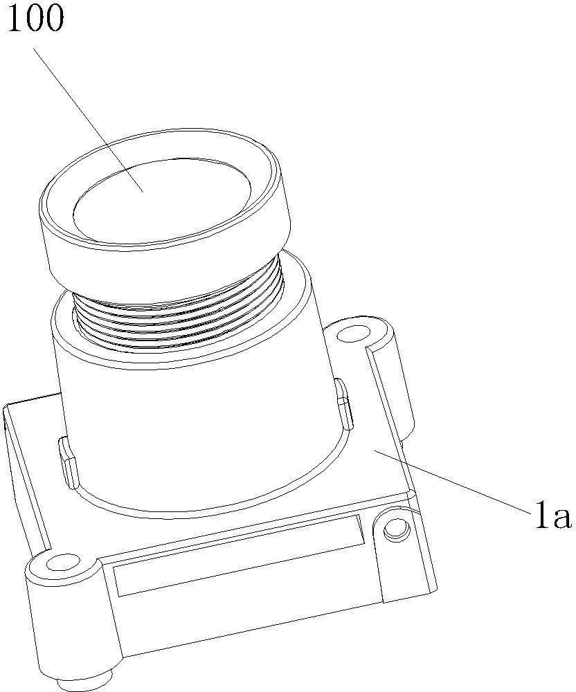
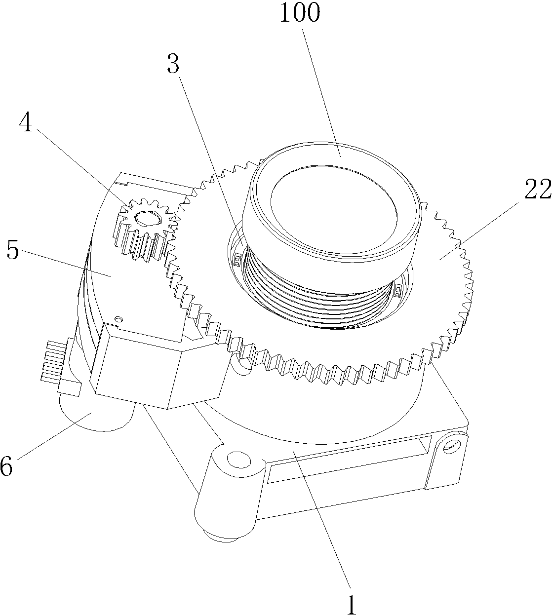
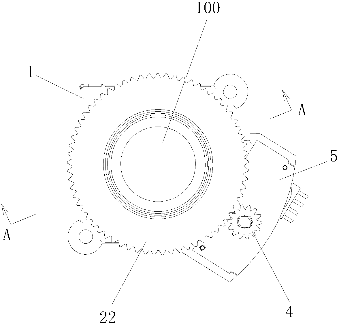
[0023] Embodiment 1. Figure 1 to Figure 8 As shown, a focusing mechanism for a monitoring lens includes a support base 1, a circular through hole 11 is provided in the middle of the support base 1, and a rotating sleeve 2 is sleeved in the circular through hole 11, and the middle of the rotating sleeve 2 There is a lens connecting sleeve 3 for assembling the lens 100, the rotating sleeve 2 is uniformly distributed with three spiral guide holes 21 along the outer peripheral surface, and the inner wall of the circular through hole 11 is uniformly distributed with three axial elongated guide grooves 111, The outer side of the support base 1 is provided with a driving gear 4, the driving gear 4 is connected with the stepping motor 6 through a reduction mechanism 5 fixed to the support base 1, and the end of the rotating sleeve 2 is provided with a driven gear 22 and the matched with the driving gear 4;

[0024] The lens connecting sleeve 3 is radially locked with three guide pin...

Embodiment 2

[0029] Embodiment two, Figure 9 As shown, what is different from the first embodiment is that the rear end of the support base 1 is provided with an assembly thread 13, which is convenient for matching with a camera with an internal thread interface.

[0030] The working principle of the present invention is as follows: the end of the guide pin 7 is limited by the elongated guide groove 111 and can only move in the axial direction, the guide pin 7 is fixed with the lens connecting sleeve 3 , and the lens 100 is mounted on the lens connecting sleeve 3 , and the guide pin 7 passes through the helical guide hole 21 on the rotating sleeve 2. When the driving gear 4 drives the driven gear 22 on the end of the rotating sleeve 2 to rotate, the helical guide hole 21 on the rotating sleeve 2 drives the guide. The pin 7 moves in the axial direction, so the lens 100 moves along the guide pin 7 in the axial direction to realize automatic or manual focus adjustment.


PUM


Abstract

The invention discloses a focusing mechanism of a monitoring lens. The focusing mechanism comprises a supporting seat, wherein a circular through hole is formed at the middle of the supporting seat, a rotating sleeve is sleeved in the circular through hole, a lens connecting sleeve is sleeved at the middle of the rotating sleeve, at least one helical guide hole is formed on the outer circumferential surface of the rotating sleeve, at least one strip-shaped guide groove is distributed on the inner wall of the circular through hole along the axial direction, a driving gear is installed at the outer side of the supporting seat, a driven gear is arranged at the end part of the rotating sleeve to be matched with the driving gear, a guide pin is fixed on the lens connecting sleeve along the radial direction, one end of the guide pin penetrates through the helical guide hole to be matched with the guide groove; preferably, three helical guide holes are uniformly distributed along the outer circumferential surface of the rotating sleeve, and three strip-shaped guide grooves are uniformly distributed on the inner wall of the circular through hole along the axial direction; the driving gear is connected with a step motor through a retarding mechanism fixed with the supporting seat. The focusing mechanism disclosed by the invention is convenient to focus, capable of realizing automatic focusing of the monitoring lens and high in focusing precision.

Description

technical field [0001] The invention relates to a focusing mechanism of a lens, in particular to a focusing mechanism of a monitoring lens. Background technique [0002] The focusing method of traditional surveillance lens is as attached figure 1 As shown, a support base 1a is arranged to be fixed with the camera, a through hole is provided in the middle of the support base 1a, and the inner surface of the through hole is provided with an inner thread to match the outer thread of the lens 100, and the lens 100 is adjusted by rotating the lens 100. The distance from the CCD of the camera to achieve focusing, but this focusing method is inconvenient to operate and cannot achieve automatic focusing, and at the same time, the focusing accuracy is low due to the influence of the thread pitch. [0003] On January 10, 2007, an invention patent with the patent number ZL200510016933.0 and the name "camera focusing mechanism" was published, which includes a motor, a motor bracke...

Claims


Application Information

Patent Timeline
Patent Type & Authority Applications(China)
IPC IPC(8): G03B13/36G02B7/09
Inventor 吴富宝徐金龙
Owner XIAMEN LEADING OPTICS
Why Eureka
Try Eureka