
A continuous automatic detection equipment for medical stents

An automatic detection and equipment technology, applied in the direction of optical testing flaws/defects, etc., can solve the problems of low efficiency of detection equipment, extrusion deformation of brackets, etc., to reduce the number of manual pick and place, reduce downtime, and improve detection efficiency.

Active Publication Date: 2016-12-14
KUNSHAN THETA MICRO
View PDF4 Cites 0 Cited by
  • Summary
  • Abstract
  • Description
  • Claims
  • Application Information

AI Technical Summary

Problems solved by technology

[0005] The purpose of the present invention is to at least solve one of the above-mentioned technical defects, especially to solve the problems of low efficiency of the existing detection equipment, easy extrusion and deformation of the bracket during the detection process, etc.

Method used

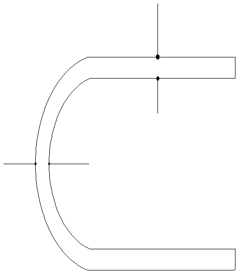
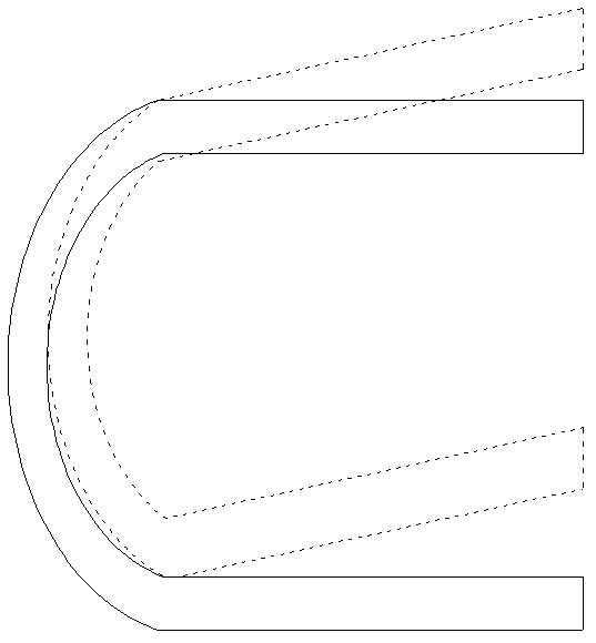
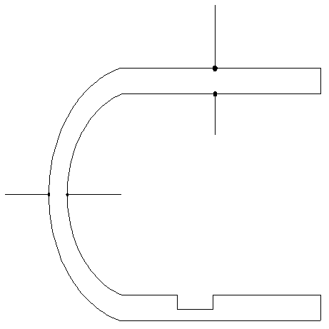

Image

  • A continuous automatic detection equipment for medical stents
  • A continuous automatic detection equipment for medical stents
  • A continuous automatic detection equipment for medical stents

Examples


Embodiment Construction

[0030] The embodiments of the present invention are described in detail below. Examples of the embodiments are shown in the accompanying drawings, in which the same or similar reference numerals indicate the same or similar elements or elements with the same or similar functions. The embodiments described below with reference to the drawings are exemplary, and are only used to explain the present invention, but should not be understood as limiting the present invention.

[0031] In the description of the present invention, it should be understood that the orientation or positional relationship indicated by the terms "upper", "lower", "inner", etc. is based on the orientation or positional relationship shown in the drawings, and is only for the convenience of describing the present invention. And to simplify the description, rather than indicating or implying that the pointed device or element must have a specific orientation, be constructed and operated in a specific orientation, ...


PUM

PropertyMeasurementUnit
diameteraaaaaaaaaa

Abstract

The invention provides a device for continuous automatic detection of a medical support. The device comprises a conveyor belt, a roller device, a two-dimensional motion platform, illumination light sources, an electronic linear array CCD, an image processing system and a display system. The roller device comprises a roller fitting seat, a driven roller, a cutting sleeve, a driving roller and a servo motor. An output shaft of the motor rotates thereby driving the driving roller to rotate. Through the cutting sleeve, the driving roller is connected to the driven roller. When rotating, the driving roller drives the driven roller to rotate. A support product is put on the driving roller and the driven roller as feeding rollers; through rotation of the two feeding rollers, the support product is driven to rotate so that through a rotation method, the support product is detected. The electronic linear array CCD transmits the acquired data to the image processing system. The device adopts a conveyor belt convey method, reduces detection device stopping time, improves detection efficiency and reduces artificial taking frequency.

Description

Technical field [0001] The invention belongs to the technical field of laser micromachining of thin-walled tubes, and relates to a detection device, in particular to a continuous automatic detection device for a medical stent. Background technique [0002] Medical stents are implanted in blood vessels to act as a support frame to keep the blood vessels open. Therefore, strict working requirements must be met. If the stent contains any rough or sharp edges, it will damage the blood cells or the implanted stent. Blood vessel wall, which will lead to further vascular disease, so that there will be potential life-threatening. Stents are generally small in diameter, about 1mm in diameter. After the laser cutting process, the size of the various cutting features on the stent is about 50~200um. Generally, small changes in parameters during the manufacturing process, such as laser power, tube diameter, or mechanical flutter, can cause defects. Because the functional failure of the sten...

Claims


Application Information

Patent Timeline
Patent Type & Authority Patents(China)
IPC IPC(8): G01N21/89
Inventor 魏志凌宁军夏发平马秀云
Owner KUNSHAN THETA MICRO
Learn More