
Flying wheel system and flying vehicle applying same

A flying wheel and body technology, applied in the field of flying cars, can solve the problems that amphibious vehicles cannot fly

Inactive Publication Date: 2013-07-24
李凤
View PDF9 Cites 28 Cited by
  • Summary
  • Abstract
  • Description
  • Claims
  • Application Information

AI Technical Summary

Problems solved by technology

[0005] In 2003, the British Gibbs launched an amphibious vehicle Aquada, which is a high-speed sports car on land. After entering the water, the four wheels of Aquada will be retracted upwards to leave the water to reduce resistance, and then Aquada becomes A high-speed speedboat that travels at high speed on the water, but this amphibious vehicle cannot fly
[0006] In 2005, Michelin launched a non-pneumatic tire. Specifically, the tire is composed of several rubber support pieces and annular rubber treads, forming many hollowed out spaces. The support pieces and treads can absorb shocks in a deformed form and It does not need to be inflated, but this air-free tire has not been used in the field of flying cars

Method used


Image

  • Flying wheel system and flying vehicle applying same
  • Flying wheel system and flying vehicle applying same
  • Flying wheel system and flying vehicle applying same

Examples


Embodiment 1

[0054]Embodiment 1: There are 4 flying wheel systems, and they are symmetrically arranged on both sides of the vehicle body 29 like an ordinary 4-wheel vehicle. An engine is provided, and the engine generates electricity to supply the hub motor 7 of the wheels and the drive motor 6 of the fan 5. The lower part of the engine compartment and the front of the car are cut in a bow shape to provide space for the front wheels to turn and reduce the air resistance when driving forward. The lower parts of both sides of the cabin are outwardly and downwardly fixedly equipped with main landing gear 34. The main landing gear 34 is in the configuration of water skis and has a certain thickness. The front landing gear 35 and the rear landing gear are respectively arranged under the engine compartment and the rear part of the vehicle body. 36, the front landing gear 35 and the rear landing gear 36 are all in the configuration of water skis, and can be controlled to put down and pack up. The ...

Embodiment 2

[0065] Embodiment 2: There are 4 flying wheel systems, and they are symmetrically arranged on both sides of the vehicle body in pairs like ordinary 4-wheeled vehicles. The position between the legs, the engine generates electricity to supply the hub motor 7 of the wheel and the drive motor 6 of the fan 5, the lower part of the driver's vehicle body position both sides is outwardly and downwardly fixedly installed with the main landing gear 34, the main landing gear 34 is in the form of Water ski configuration, and certain thickness is arranged, and front undercarriage 35 and rear undercarriage 36 are respectively provided with under the vehicle body front part and rear, and front undercarriage 35 and rear undercarriage 36 all are water ski configurations, and can The air intake of the engine is in the upper part of the front part of the vehicle body, and the radiator and exhaust pipe are arranged on the upper part of the vehicle body behind the driver.

[0066] Embodiment two ...


PUM


Abstract

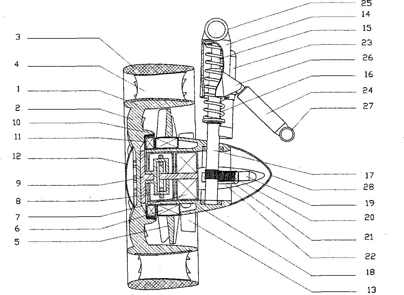
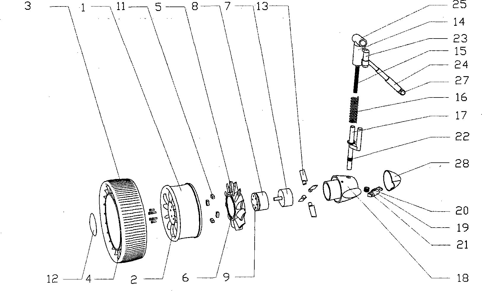
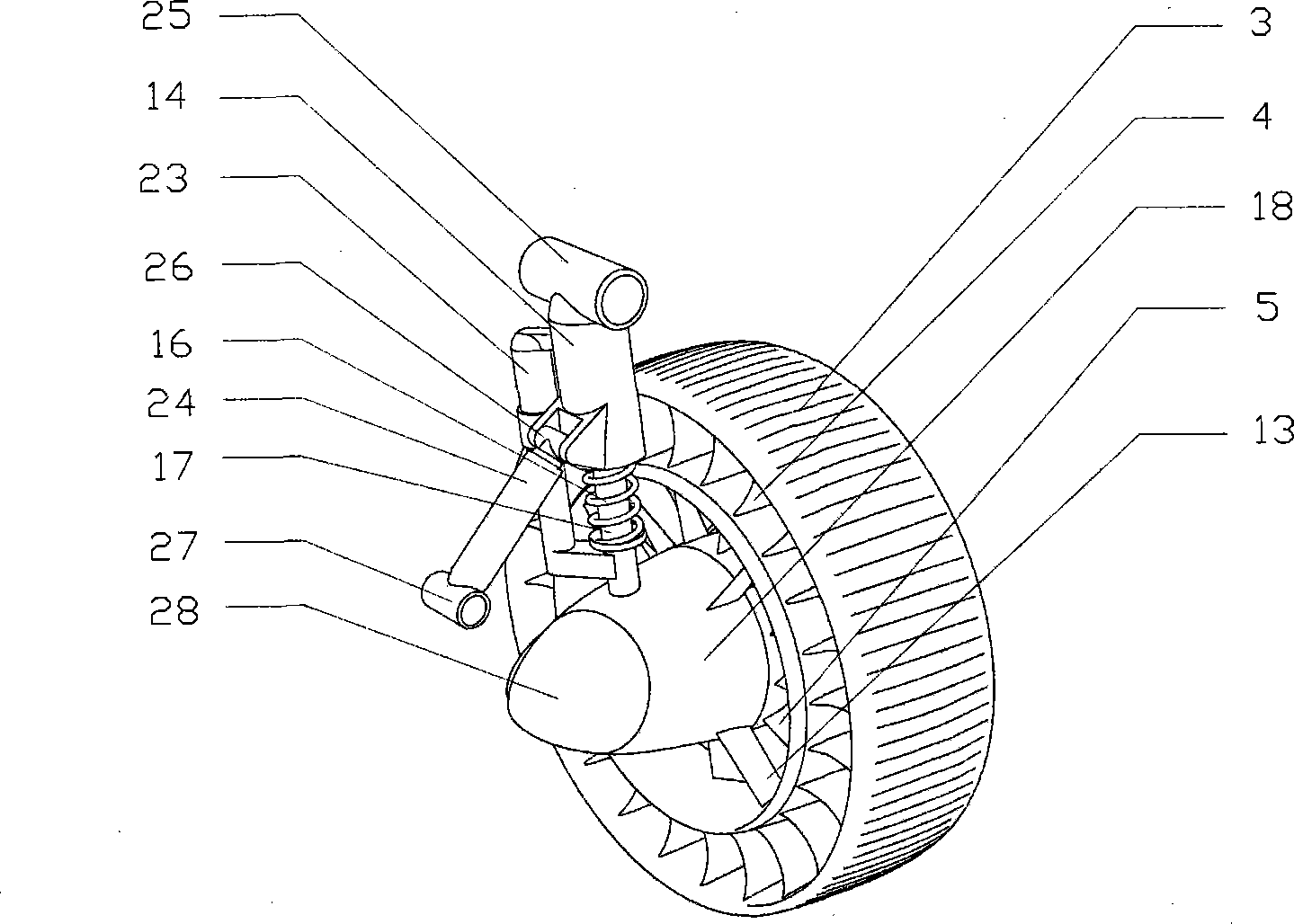
The invention discloses a flying wheel system. The flying wheel system comprises a wheel hub with radial spokes, a tire formed by a support piece and a tread, and a wheel hub motor, wherein the spokes and the rim of the wheel hub of a flying wheel as well as the sections of the support piece and the tread of the tire are wing-shaped, and the wheel hub motor, a fan, a driving motor and a steering mechanism are all installed on a basic structure; the top end of a candle type suspension frame is hinged outside a vehicle body, and the lower end of the candle type suspension frame is mounted on the basic structure; and a telescopic driving device is hinged between the candle type suspension frame and the vehicle body. According to the flying vehicle system disclosed by the invention, thrust can be generated by speeding up air above the wheel and downwards spraying the air through the fan, upward lifting force can be generated by the rim and the tread with the wing-shaped sections, and the flying wheel and the candle type suspension frame can be unfolded and folded relative to the vehicle body by the telescopic driving device. A flying vehicle adopting the flying wheel system disclosed by the invention can be switched among states of a vehicle, a helicopter, a plane with fixed wings and a ship, and realizes the corresponding functions at the same time.

Description

technical field [0001] The invention relates to a wheel, in particular to a flying wheel system and a flying car using the flying wheel system. Background technique [0002] In 1949, American Fulton Taylor introduced a flying car for the first time. This flying car is divided into two parts, one part is a small car that can drive on the ground; the other part is a flying device, specifically The rear fuselage is equipped with wings, empennage, aero-engines and propellers. When the flying device is installed behind a small car, the two form a conventional layout aircraft, and the four wheels of the car part become the take-off and landing plane of the aircraft. wheel, the cockpit of a car becomes the cockpit of an airplane. This kind of flying car can realize the two functions of car driving and airplane flying, but it is very inconvenient to take off from the airport runway when flying. When the car is in state, it is necessary to fold the wings and tail of the flying devic...

Claims


Application Information

Patent Timeline
Patent Type & Authority Applications(China)
IPC IPC(8): B60F5/02
Inventor 龙川
Owner 李凤
Learn More