Electric control backwashing filter

A backwashing and filter technology, applied in the field of filters, can solve the problems of high labor intensity, shortened service life of filter elements, and low degree of automation, and achieve the effect of improving filtration efficiency, prolonging service life, and high degree of automation.

Active Publication Date: 2013-07-24
NINGBO LONG WALL FLUID KINETIC SCI TECH
View PDF7 Cites 7 Cited by
  • Summary
  • Abstract
  • Description
  • Claims
  • Application Information

AI Technical Summary

Problems solved by technology

Its disadvantages are: many existing backwash filters are used on supports in coal mines. Due to the need for frequent manual operations, the degree of automation is low and the labor intensity is high. Due to the special working conditions in coal mines, the operation is very inconvenient.
The website of the State Intellectual Property Office discloses an electric backwash filter, which solves the problem that the existing backwash filter requires manual operation. It is difficult for the piston and valve core to move up and reset. Since the sewage discharge outlet is connected with the spring installation cavity, it is easy to cause spring corrosion and valve core stuck; and the sewage discharge channel and the liquid inlet channel have a common channel, which is prone to impurity residues during sewage discharge In the public channel, the resistance increases when the liquid is re-introduced, and the impurities are washed into the filter element cavity and attached to the filter element when the liquid is re-introduced, which not only reduces the filtration efficiency of the backwash filter, but also shortens the service life of the filter element.

Method used


Image

  • Electric control backwashing filter
  • Electric control backwashing filter
  • Electric control backwashing filter

Examples


Embodiment Construction

[0015] The present invention will be further described below in conjunction with the accompanying drawings and specific embodiments.

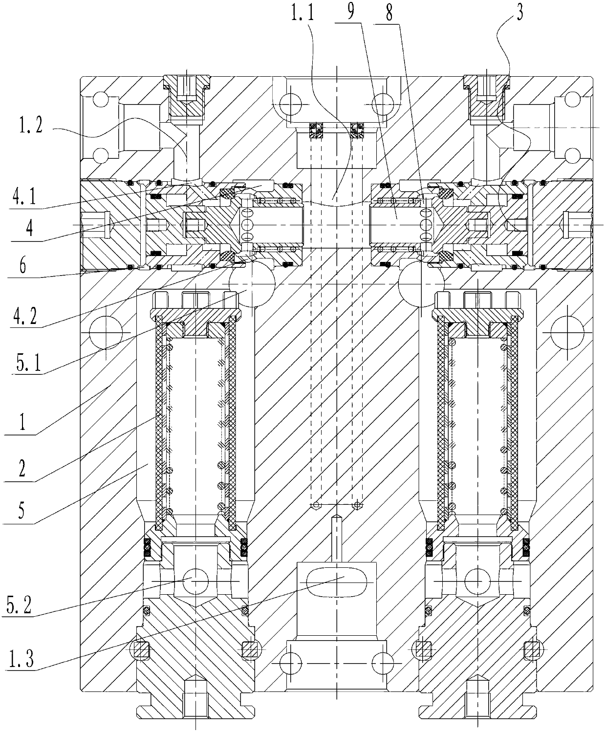
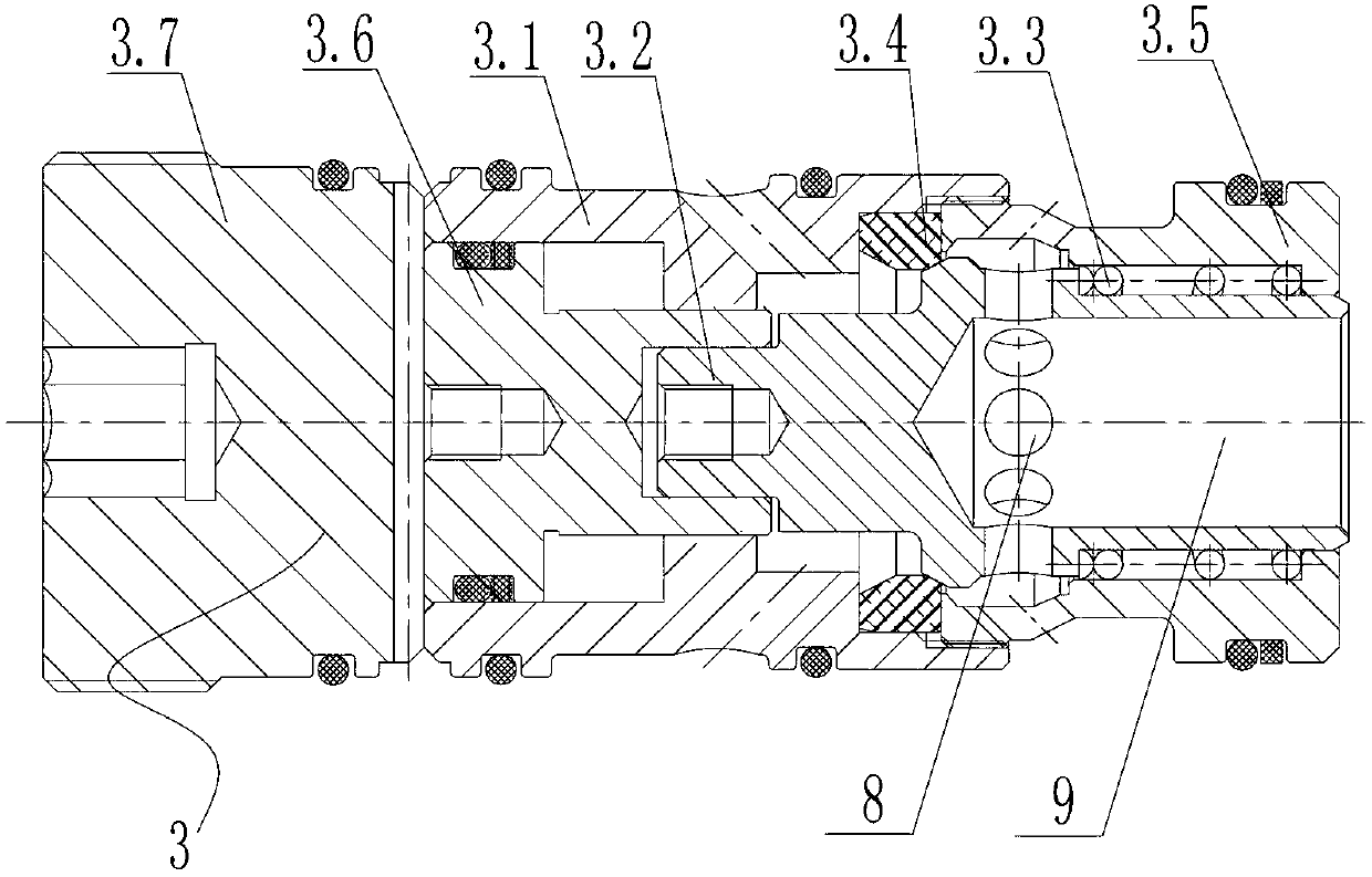
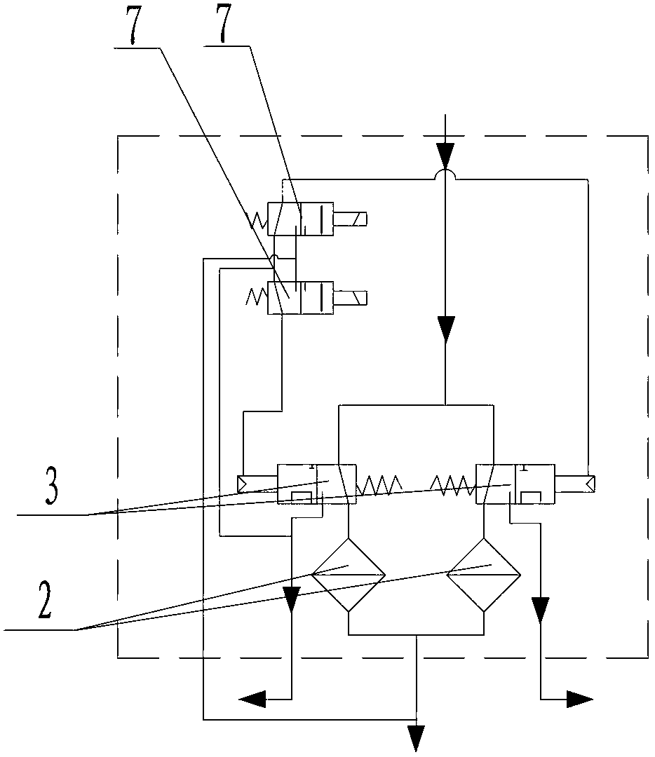
[0016] see Figure 1 ~ Figure 4 As shown, the present invention is an electronically controlled backwash filter, which includes a valve body 1, and the valve body 1 is provided with at least two spool cavities 4 equipped with spool assemblies 3 and equal in number to the spool cavities 4 And the filter cavity 5 of the filter element 2 is installed, and each valve core assembly 3 is provided with a liquid inlet 8, and the valve body 1 is provided with a liquid inlet channel 1.1 communicated with the liquid inlet 8 and connected with the filter The working fluid outlet 5.2 of the cavity 5 is connected to the liquid outlet channel 1.3, and each valve core cavity 4 is provided with a liquid outlet 4.2 and a sewage outlet 4.1, and the liquid outlet 4.2 of each valve core cavity 4 It communicates with the working fluid inlet 5.1 of the corresponding...


PUM


Abstract

The invention relates to an electric control backwashing filter, which comprises a valve body, and the valve body is internally equipped with at least two valve core chambers installed with valve core components as well as filter chambers installed with filter cores and the quantity of the filter chamber is equal to that of the valve core chamber; each valve core component is provided with one liquid inlet, and each valve core chamber is provided with a liquid outlet and a sewage discharge outlet; the liquid outlet of each valve core chamber is communicated with the operating fluid inlet of the corresponding; the valve core component is also provided with a hydraulic control port, and a hydraulic control channel is equipped in the valve body for communicating with the hydraulic control port; the valve body is provided with an electromagnetic pilot valve which is communicated with the hydraulic control channel for controlling the movement of the valve core of the valve core component in the valve core chamber, thereby respectively communicating with the liquid outlet and the liquid inlet or the liquid outlet and the sewage draining exit. The electric control backwashing filter has the advantages of higher automation degree, convenient operation, incorruptible spring, non-dead locking of the valve core, improved filtering efficiency and prolonged usage period.

Description

technical field [0001] The invention relates to a filter, in particular to an electronically controlled backwash filter used on a coal mine underground support. Background technique [0002] The existing backwash filter mainly includes a valve body, two filter elements arranged in the valve body and two manual liquid inlet stop valves arranged in the valve body. When filtering the emulsion, the emulsion medium flows into the two inlets respectively from the liquid inlet. The liquid shut-off valve flows into the corresponding filter elements, and the emulsions filtered by the two filter elements meet and flow out in the liquid outlet channel. When backwashing, close a shut-off valve and open the backwash port at the same time. The inner cavity of the filter element where the filter element corresponding to the closed inlet shut-off valve is located has no high-pressure emulsion and the pressure drops, resulting in emulsification after being filtered by another filter element....

Claims


Application Information

Patent Timeline
Patent Type & Authority Applications(China)
IPC IPC(8): B01D35/12E21D15/51
Inventor 王金辉应永华姚志生刘庆华
Owner NINGBO LONG WALL FLUID KINETIC SCI TECH
Why Eureka
Try Eureka