
Controllable gain circuit

A gain circuit and circuit technology, applied in the direction of gain control, improvement of control circuits for reducing distortion, electrical components, etc., can solve the problems of small controllable gain bandwidth, small gain range, poor linearity, etc., to achieve small spurious, The effect of large dynamic range and high IP3

Active Publication Date: 2013-07-17
创远信科(上海)技术股份有限公司
View PDF5 Cites 2 Cited by
  • Summary
  • Abstract
  • Description
  • Claims
  • Application Information

AI Technical Summary

Problems solved by technology

The analog type is divided into two types. One is composed of triode circuits. The advantage is that key indicators such as IP3 and spurious are better. The disadvantage is that the controllable gain bandwidth is small, the accuracy is poor, the gain range is small, and the circuit is more complicated.
The other is to adjust the gain by analog voltage. The advantage is that the IP3, spurious and other indicators are better, and it can achieve a larger gain bandwidth. The disadvantage is that the linearity is poor, the gain range is small, and the accuracy is poor. With the change of the gain , the noise figure also changes with

Method used


Image

  • Controllable gain circuit

Examples


Embodiment

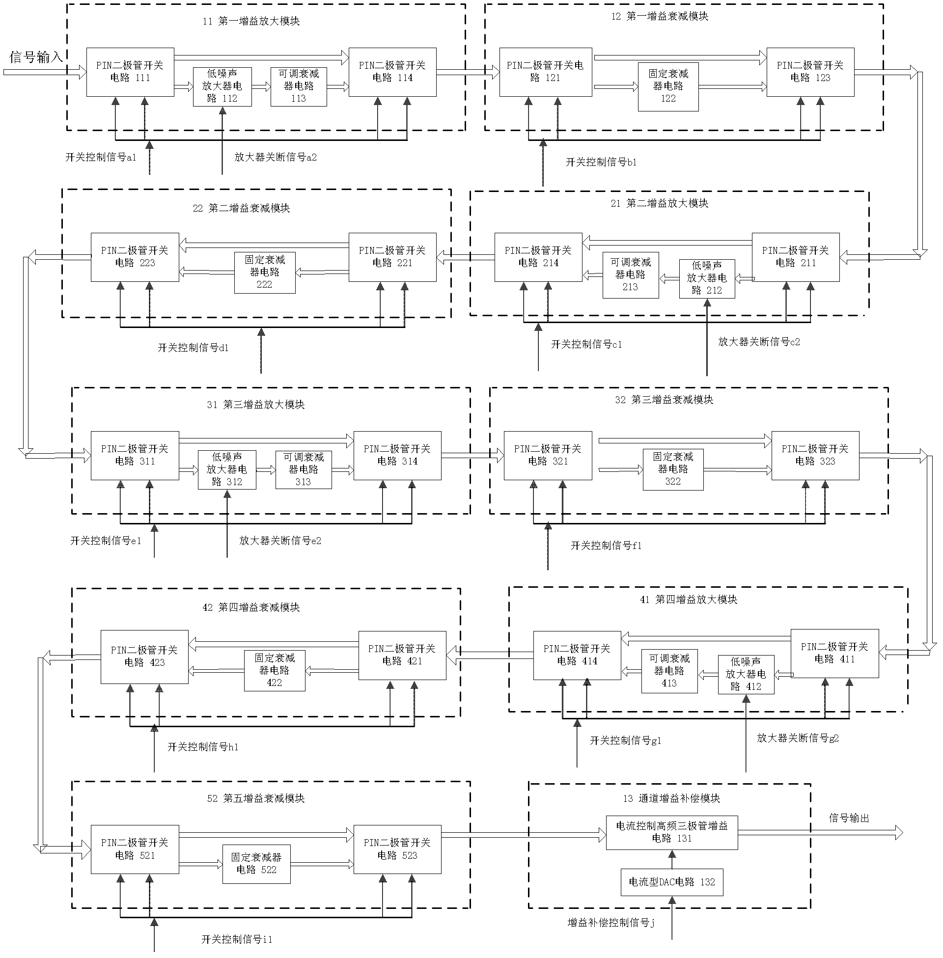
[0023] Such as figure 1 As shown, a controllable gain circuit is composed of 10 gain adjustment modules, which are sequentially connected first gain amplification module 11, first gain attenuation module 12, second gain amplification module 21, second gain attenuation module Module 22 , third gain amplifying module 31 , third gain attenuating module 32 , fourth gain amplifying module 41 , fourth gain attenuating module 42 , fifth gain attenuating module 52 and channel gain compensation module 13 .

[0024] Except for the channel gain compensation module 13, the other modules all include two signal channels, a through channel and a gain adjustment channel, and channel selection is controlled by a switch circuit arranged at both ends of the through channel and the gain adjustment channel. The gain amplifying value of the first gain amplifying module 11 and the third gain amplifying module 31 is 20dB, the gain amplifying value of the second gain amplifying module 21 and the fourt...


PUM


Abstract

The invention relates to a controllable gain circuit which comprises a first gain amplification module, a first gain reduction module, a second gain amplification module, a second gain reduction module, a third gain amplification module, a third gain reduction module, a fourth gain amplification module, a fourth gain reduction module, a fifth gain reduction module and a channel gain compensation module which are sequentially connected. Compared with the prior art, the controllable gain circuit has the advantages of small signal distortion, large dynamic range and the like.

Description

technical field [0001] The invention relates to a controllable gain circuit, in particular to a controllable gain circuit with wide band, small signal distortion and large dynamic range. Background technique [0002] Controllable gain circuits are widely used in receivers, and the use of controllable gain circuits makes it possible for receivers to analyze signals with a large dynamic range. There are two main types of existing controllable gain circuits, one is digital and the other is analog. At present, the digital controllable gain is mainly an integrated circuit. The integrated circuit chip is controlled by the digital control interface to realize the amplification and attenuation of the gain. The advantage is that the volume is small and the control logic is simple. The disadvantage is that the gain adjustment range is small. Improve the dynamic range, but IP3, spurious and other indicators are affected, resulting in distortion, and the in-band flatness is poor when t...

Claims


Application Information

Patent Timeline
IPC IPC(8): H03G1/04H03G3/20
Inventor 白皓
Owner 创远信科(上海)技术股份有限公司
Features
  • Generate Ideas
  • Intellectual Property
  • Life Sciences
  • Materials
  • Tech Scout
  • Unparalleled Data Quality
  • Higher Quality Content
  • 60% Fewer Hallucinations
Learn More