


Quick Research
Generate reliable direction feasibility study reports for your R&D in just a few steps.

Technical Q&A
Discover and master advanced knowledge NOW. Basics, ideas, possibilities, all at once.

Find Solutions
As an expert in R&D theories, this can generate solutions to your technical problems instantly.

Evaluate Feasibility
Analyze your overall solution with one click, know your potential R&D risks in advance.

Monitor Landscape
Get weekly tech updates, stay abreast of the latest tech innovations and key insights.
Magnet force device
A magnet and magnetic technology, applied in electromechanical devices, electrical components, generators/motors, etc., can solve the problem that permanent magnet DC motors cannot have magnets at the same time
- Summary
- Abstract
- Description
- Claims
- Application Information
AI Technical Summary
Problems solved by technology
Method used
Image


Examples
Embodiment 1
[0040] Embodiment 1: Utilize the thrust device of 4 directions of suction, repulsion, and magnet magnetic force
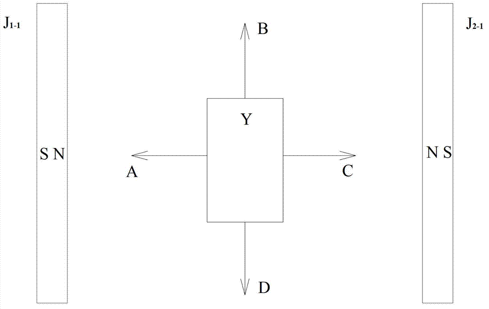
[0041] 1). Figure 1 is a schematic diagram of the structure of the attraction, repulsion, and magnetic force of the magnet in different directions
[0042] The static magnets J1-1, J2-1 and the static magnets J1-2, J2-2 are respectively fixed on two planks M, and the two N poles are opposite to form an N pole (S pole) space. Make a U-shaped aluminum frame L and place it in the N pole space. Cross a copper tube T on the U-shaped aluminum frame L, and place a moving magnet Y with a hole in the middle on the copper tube T. The direction of the magnetic pole axis of the moving magnet Y is consistent with the direction of the copper tube T. The moving magnet Y can Swipe on T. The moving magnet Y and the copper tube T are placed in the center of the N pole space. The aluminum frame L and the wooden board M are fixed with a shaft and a bearing Z, located at the center,...
Embodiment 2
[0063] Embodiment 2: Two magnets provide the magnetic field and one magnet provides the magnetic pole axis magnetic field and only use the short-distance linear motion device of the magnet force
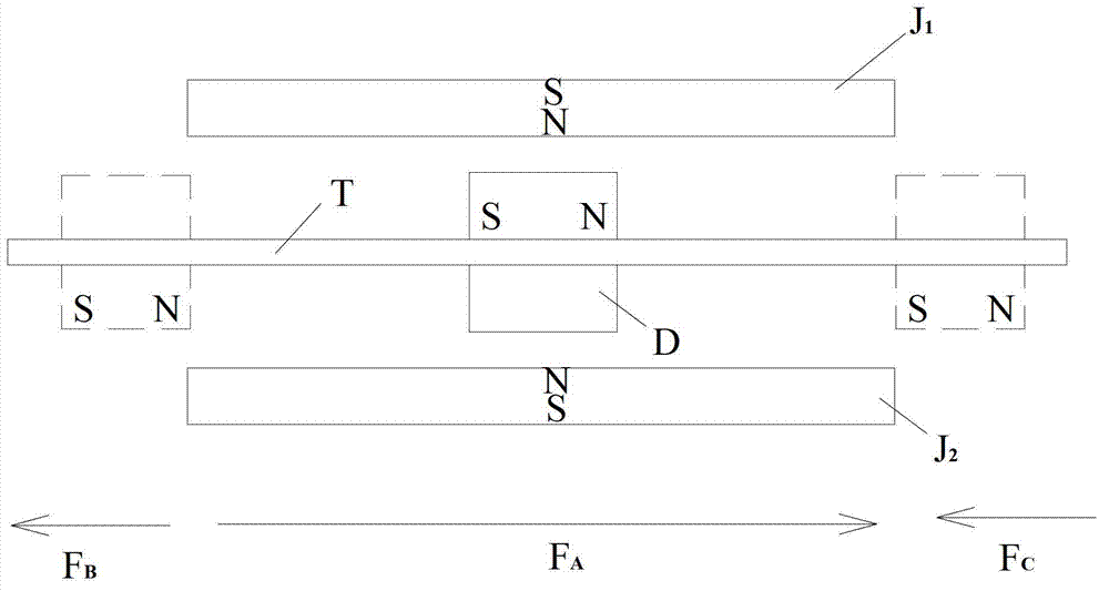
[0064] figure 2 It is a schematic diagram of the structure in which the attraction force, repulsion force and magnetic force of the magnet exist in the same direction.
[0065] Static magnets J1 and J2 have S poles on the outside and N poles on the inside, and moving magnet D is a cylindrical shape with a central hole, with N poles on the right and S poles on the left. A copper rod T passes through the center hole, and the moving magnet D can slide on the copper rod T, and the moving magnet D and the copper rod T are placed in the magnetic fields of the static magnets J1 and J2. The internal connection line between the N pole and the S pole of the magnet is called the magnetic pole axis of the magnet. When the direction of the magnetic pole axis of the moving magnet is 90°±45° to t...
Embodiment 3
[0066] Embodiment 3: One magnet provides two magnetic fields and two magnets provide the magnetic pole axis magnetic field and only uses the short-distance linear motion device of the magnet force
[0067] image 3 It is a schematic diagram of the short-distance linear motion structure using the magnetic force of a magnet.
[0068] image 3is a top view. The length of the moving magnet D is longer than that of the static magnet. The moving magnet D provides a magnetic field, and one side is an N pole, and the other side is an S pole. Moving magnet D is installed on the support that has 4 wheels L, can roll forward on plane or track. The static magnets J1 and J2 are respectively installed on supports on both sides of the magnetic field of the moving magnet D, and the supports are fixed on a plane or a track. The S-N magnetic pole axis of J1 is close to the N pole of D, and the N-S magnetic pole axis of J2 is close to the S pole of D. The directions of the magnetic pole axe...
PUM
| Property | Measurement | Unit |
|---|---|---|
| Arc angle | aaaaa | aaaaa |
Abstract
Description
Claims
Application Information
 - R&D Engineer
- R&D Manager
- IP Professional
- Industry Leading Data Capabilities
- Powerful AI technology
- Patent DNA Extraction
Browse by: Latest US Patents, China's latest patents, Technical Efficacy Thesaurus, Application Domain, Technology Topic, Popular Technical Reports.
© 2024 PatSnap. All rights reserved.Legal|Privacy policy|Modern Slavery Act Transparency Statement|Sitemap|About US| Contact US: help@patsnap.com