
adjustable wrench

A technology of adjustable wrench and wrench, which is applied in the field of wrench, can solve the problems of small torque and slow speed of worm gear, achieve the effect of reducing the requirement of matching precision and improving force component

Active Publication Date: 2017-10-27
HANGZHOU GREAT STAR TOOLS
View PDF8 Cites 0 Cited by
  • Summary
  • Abstract
  • Description
  • Claims
  • Application Information

AI Technical Summary

Problems solved by technology

[0004] In the prior art, the helix of the thread on the worm wheel is one, which is a single-thread thread, and the speed of rotating the worm wheel to move the movable part is relatively slow, and the torque that the single-thread worm wheel can bear is small

Method used


Image

  • adjustable wrench
  • adjustable wrench
  • adjustable wrench

Examples


Embodiment Construction

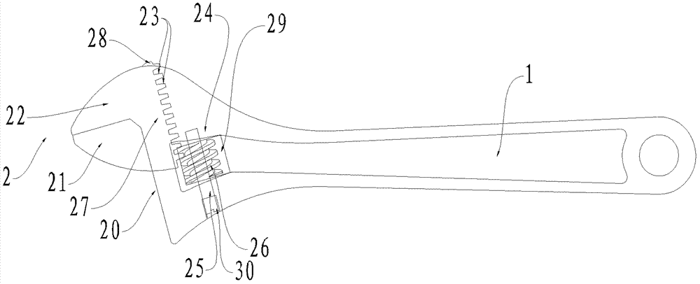
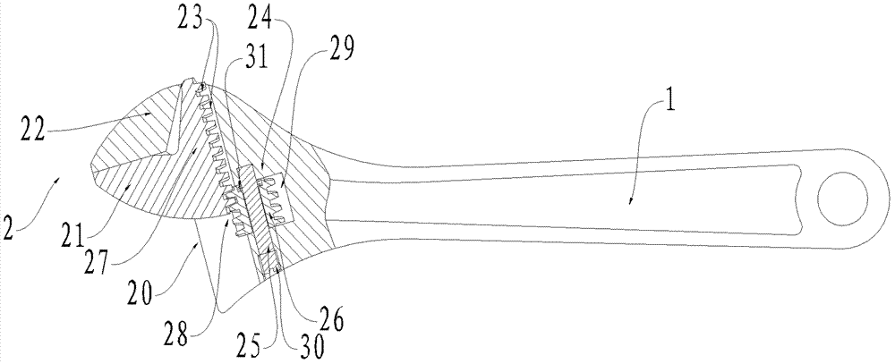
[0029] Such as figure 1 As shown, the adjustable wrench of the first embodiment of the present invention includes a wrench body and a worm gear 24 , and the wrench body includes a handle 1 and a working part 2 . The working part includes a fixed part 22 , a movable part 21 and a chute 20 . The fixing part 22 is located at the upper end of the wrench body and at the side of the wrench body. The chute 20 is close to one end of the fixing portion 22 and extends laterally. Both ends of the chute 20 are open, and a part of the upper end of the chute 20 is also open.

[0030] The lower end of the movable part 21 is disposed in the slide slot 20 to move toward or away from the fixed part 22 . The lower end of the movable part 21 includes a neck 27 and a slider 28 , the slider 28 is located at the bottom of the neck 27 and is roughly cylindrical. The neck 27 and the slider 28 are arranged in the chute 20 . On the bottom edge of the slider 28 , there is provided a tooth portion 23 ...


PUM


Abstract

The invention discloses an adjustable wrench, comprising a wrench body and a worm wheel; the wrench body includes a handle and a working part; the working part includes a fixed part, a movable part and a chute; the movable part The lower end of the movable part is set in the chute, and the bottom edge of the lower end of the movable part is provided with a tooth part; the working part also includes a through hole, and the worm wheel is set in the through hole and meshes with the tooth part; When the worm wheel is rotated, the worm wheel interacts with the tooth portion, thereby driving the movable portion to move toward or away from the fixed portion; the thread of the worm wheel has at least two helical lines. The adjustable wrench of the invention can quickly adjust the distance between the movable part and the fixed part, and increase the torque that the worm wheel can bear.

Description

technical field [0001] The invention relates to a wrench, in particular to an adjustable wrench. Background technique [0002] An adjustable wrench (adjustable wrench) is generally composed of a wrench body, a worm gear, a pin shaft, a spring, etc., and is a tool for tightening or loosening angled screws or nuts. [0003] The wrench body includes a handle and a working part. The working part includes a fixed part, a movable part and a chute. The lower end of the movable part is arranged in the chute to move toward or away from the fixed part. The bottom edge of the lower end of the movable part is provided with teeth. The teeth mesh with the threads on the worm gear. Because the screw thread on the worm wheel meshes with the tooth portion of the bottom edge of the lower end of the movable part, turning the worm wheel can drive the movable part to move toward or away from the fixed part along the chute. [0004] In the prior art, there is one helix of the thread on the w...

Claims


Application Information

Patent Timeline
Patent Type & Authority Patents(China)
IPC IPC(8): B25B13/14
CPCB25B13/14
Inventor 王缗
Owner HANGZHOU GREAT STAR TOOLS
Learn More