
Fingerprint recognition controller

A fingerprint identification and controller technology, applied in the field of locks, can solve the problems of increased cost, large size, and no operation panel, and achieve the effects of low design, development and manufacturing costs, high portability, and high reliability

Inactive Publication Date: 2013-07-10
杨浩
View PDF6 Cites 5 Cited by
  • Summary
  • Abstract
  • Description
  • Claims
  • Application Information

AI Technical Summary

Problems solved by technology

[0004] Although the application of this fingerprint recognition module in the prior art is relatively common, it has many disadvantages.
The fingerprint collector, control board, key board, etc. included in this fingerprint identification module are independent and dispersed structures. They are bulky, have no fixed position, and no operation panel for normal operation. The product is pre-designed in the reserved position, so this kind of module cannot be used as an individual that can be used independently as a whole, and thus cannot be directly embedded as a whole in traditional product solutions such as locks and cabinets, and requires a new secondary development and design in the later stage , At the same time, each product needs to be targeted (according to the specifications and dimensions of each component of the traditional fingerprint module) to open a new product shell and internal structure mold for production and manufacturing
To sum up, the versatility, safety, convenience, and reliability of this fingerprint identification module are poor, which in turn causes inconvenience in the manufacture of fingerprint locks and increases in cost.

Method used


Image

  • Fingerprint recognition controller
  • Fingerprint recognition controller
  • Fingerprint recognition controller

Examples


Embodiment Construction

[0033]The technical solutions of the various embodiments of the present invention will be clearly and completely described below in conjunction with the accompanying drawings. Apparently, the described embodiments are only some of the embodiments of the present invention, not all of them. Based on the embodiments of the present invention, all other embodiments obtained by persons of ordinary skill in the art without making creative efforts belong to the protection scope of the present invention.

[0034] In Embodiment 1 of the present invention, the fingerprint identification controller includes:

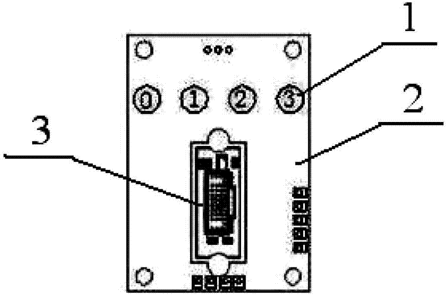
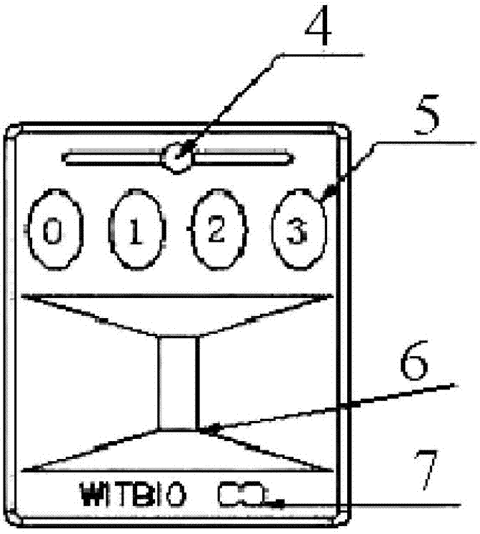
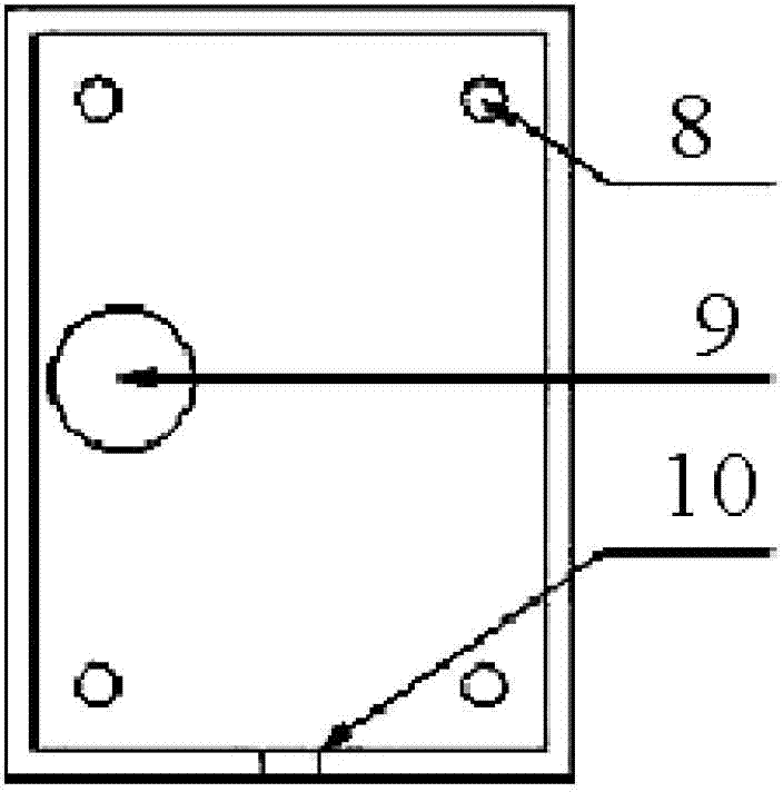
[0035] Fingerprint collection element, control main board, operation panel and rear fixed cover, wherein, a fingerprint collection window is provided on the operation panel, and the fingerprint collection element is connected with the operation panel for collecting fingerprints on the operation panel window to collect fingerprint information;

[0036] Wherein, the control board inc...


PUM


Abstract

The invention relates to the field of locksets and in particular relates to a fingerprint recognition controller which can improve the convenience in use, the security, the reliability, the generality and the transportability, and greatly reduce the development and manufacturing costs of a terminal application product, so as to improve the popularization and application of the product. The structure of the fingerprint recognition controller comprises a fingerprint acquisition element, a control mainboard, an operation panel and a rear fixing cover, wherein a fingerprint acquisition window is arranged on the operation panel; the fingerprint acquisition element is connected with the operation panel and is used for acquiring fingerprint information through the fingerprint acquisition window on the operation panel; the control mainboard comprises the following structures integrated on the control mainboard: an information storage structure for storing fingerprint information, an information recognition control structure for comparing fingerprint information, a physical function selection and setting mechanism, an input structure for receiving instruction information and an output mechanism for controlling driving equipment and prompting information; and the control mainboard is connected with the fingerprint acquisition element and is integrally fixed with the operation panel and the rear fixing cover.

Description

technical field [0001] The invention relates to the field of locks, in particular to a fingerprint recognition controller. Background technique [0002] Fingerprint identification technology is to match a person's identity with his own fingerprint. By comparing the instantly read fingerprint with the pre-saved fingerprint, the real identity of the person can be verified. Each person's skin texture (including fingerprints) is different in pattern and intersection, which means that each person's skin texture is unique and normally remains unchanged throughout life. Relying on this uniqueness and stability, we can confirm a person's identity through fingerprint recognition technology. [0003] The fingerprint identification module used in the prior art uses a fingerprint collector, a control board, a key board, etc. as the main components, and each independent component is connected with a data line; Fingerprint collection components and a less secure picture-based fingerprin...

Claims


Application Information

Patent Timeline
Patent Type & Authority Applications(China)
IPC IPC(8): G07C9/00
Inventor 杨浩
Owner 杨浩
Learn More