
Modularized joint displacement sensor applied to robot

A technology of modular joints and displacement sensors, applied in the field of displacement sensors, can solve problems such as unfavorable installation and maintenance, general sensors cannot meet the special requirements of robots, and cumbersome, and achieves improved operating comfort, convenient wiring, and flexible installation methods. Effect

Active Publication Date: 2013-07-10
STATE GRID INTELLIGENCE TECH CO LTD
View PDF6 Cites 4 Cited by
  • Summary
  • Abstract
  • Description
  • Claims
  • Application Information

AI Technical Summary

Problems solved by technology

[0004] However, general-purpose sensors cannot meet the special requirements of robots
For example, there must be a rotation mechanical limit; the sensor has a large force, so a coupling must be installed when using it; at the same time, the robot is a motion mechanism, and the cable routing structure must be strictly designed; in this way, in order to meet the special needs of the robot Requirements, when general-purpose sensors are applied to robots, they are often cumbersome, which is not conducive to installation and maintenance

Method used


Image

  • Modularized joint displacement sensor applied to robot

Examples


Embodiment 1

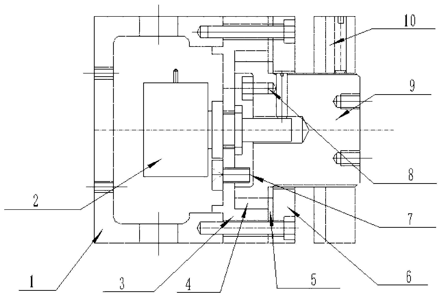
[0030] Such as figure 1 As shown, the present invention includes a housing 1 with one side opening and an output shaft 9 fixed at the opening of the housing 1 through a sliding bearing. The sliding bearing includes a bearing seat 3 and a bearing cover 6, and the housing 1 is provided with a fixed bearing seat 3 The limit screw II7, the housing 1 is fixed on the frame, the output shaft 9 is fixed on the rotating part, the interior of the housing 1 is installed with a linear potentiometer 2, and the lower and upper sides of the housing 1 are respectively provided with for input and output. Out of the hole for the cable, the cable is soldered to the linear potentiometer 2. The potentiometer shaft of the linear potentiometer 2 passes through the bearing seat 3 and is stuck in the output shaft 9. There is a gap between the output shaft 9 and the end of the potentiometer shaft to ensure that the potentiometer shaft only bears torque and does not bear axial or radial loads; Moreover...

Embodiment 2

[0034] The output shaft 9 is fixed on the frame, the housing 1 is fixed on the rotating part, and the output shaft 9 drives the potentiometer shaft to rotate, thereby converting the rotation of the output shaft 9 into an electrical signal. The other parts are the same as those in Embodiment 1 and will not be described in detail.

[0035] The present invention is equally applicable to other automatic devices that have the same requirements as robots.


PUM


Abstract

The invention discloses a modularized joint displacement sensor applied to a robot. Mechanical rotation is converted into voltage signal output so as to provide position and speed feedback to automatic equipment. The modularized joint displacement sensor has the advantages of being capable of bearing large axial and radial loads, being compact in structure, light in weight, small in size, reliable in performance and the like. The modularized joint displacement sensor comprises a shell with an opening at one side, and an output shaft which is fixed at the opening of the shell through a bearing; the bearing comprises a bearing block and a bearing cover; one of the shell and the output shaft is fixed on a frame, and the other one of the shell and the output shaft is fixed on a rotary component; a linear potentiometer is arranged inside the shell; a potentiometer shaft of the linear potentiometer passes through the bearing block and is clamped in the output shaft; and a clearance is formed between the output shaft and the tail end of the potentiometer shaft. Therefore, the potentiometer just bears torque and does not bear the axial or radial load; and the shell or the output shaft fixed on the rotary component drives the potentiometer shaft to rotate so as to convert the rotation of the output shaft or the shell into an electric signal.

Description

technical field [0001] The invention relates to a displacement sensor, in particular to a modular joint displacement sensor applied to a robot. Background technique [0002] With the research and technological progress of automation equipment and robots, high-performance sensors have become an important part of automation equipment. The sensors used for motion control mainly include: resolvers, encoders, etc. The principle of these sensors is to convert the displacement and speed of automatic equipment into analog or digital signal output. The control system performs motion control based on these signals. At present, these sensor technologies are becoming more and more mature, the accuracy of the sensors is getting higher and higher, and the size is getting smaller and smaller. [0003] The miniaturization of sensors also brings some problems. The input shafts of sensors such as resolvers and encoders generally cannot bear large axial and radial forces. As a general-purp...

Claims


Application Information

Patent Timeline
IPC IPC(8): G01D5/165G01B7/30
Inventor 戚晖孙玉田
Owner STATE GRID INTELLIGENCE TECH CO LTD
Learn More