Electro-hydraulic gate valve

A plug-in valve, electro-hydraulic technology, applied in the direction of sliding valves, valve devices, engine components, etc., can solve the problems of poor sealing effect at the guide rail, and achieve good sealing performance, high wear resistance, flexible and reliable valve opening and closing Effect

Inactive Publication Date: 2013-07-10
扬州市飞龙气动液压设备有限公司
View PDF0 Cites 0 Cited by
  • Summary
  • Abstract
  • Description
  • Claims
  • Application Information

AI Technical Summary

Problems solved by technology

[0002] The existing electro-hydraulic slide valve includes a frame, and the frame includes two vertical plates, one end of the two vertical plates is connected by a first horizontal plate, the other end of the two vertical plates is connected by a second horizontal plate, and the first horizontal plate Two intermediate plates are arranged between the plate and the second horizontal plate, and the two ends of the two intermediate plates are respectively connected with the corresponding vertical plates; each vertical plate is respectively connected with an oil cylinder, and an inserting plate is arranged between the two oil cylinders, The inserting plate is arranged between the two middle plates, and the telescopic ends of the two oil cylinders are respectively connected to the inserting plate; respectively connected to the first horizontal plate, the two vertical plates between the first horizontal plate and the middle plate A set of guide rails arranged in pairs, the sealing effect at the guide rails of this structure is poor

Method used


Image

  • Electro-hydraulic gate valve
  • Electro-hydraulic gate valve
  • Electro-hydraulic gate valve

Examples


Embodiment Construction

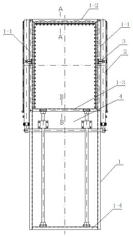
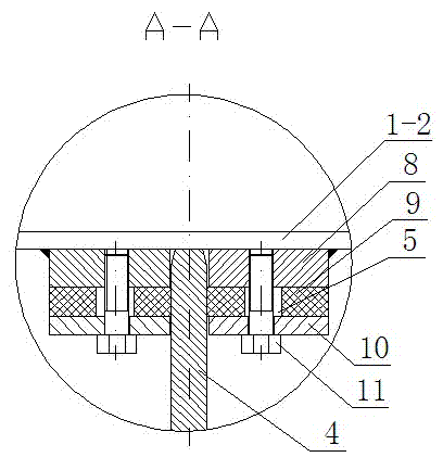
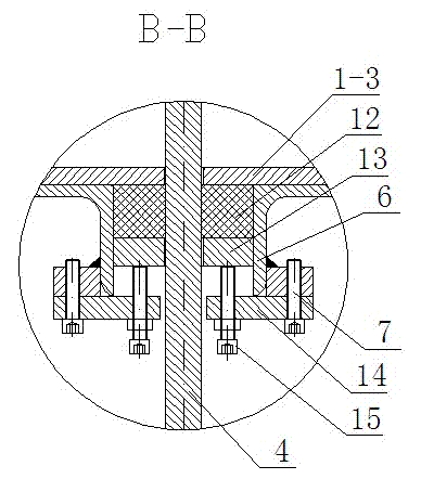
[0010] Such as figure 1 As shown, it is an electro-hydraulic slide valve, including a frame 1, and the frame 1 includes two vertical plates 1-1, and one end of the two vertical plates 1-1 is connected by a first horizontal plate 1-2, and the two vertical plates 1-1 The other end of -1 is connected by the second horizontal plate 1-4, and two intermediate plates 1-3 are arranged between the first horizontal plate 1-2 and the second horizontal plate 1-4, and the two intermediate plates 1-3 The two ends are respectively connected with the corresponding vertical boards 1-1. Each vertical plate 1-1 is respectively connected to the oil cylinder support 3, and each oil cylinder support 3 is respectively connected to the oil cylinder 2, and an inserting plate 4 is arranged between the two oil cylinders 2, and the inserting plate 4 is arranged on two intermediate plates 1-3 Between, the telescoping end of two oil cylinders 2 is connected with inserting plate 4 respectively.

[0011] S...


PUM


Abstract

The invention discloses an electro-hydraulic gate valve and relates to the structure of a control valve on a flue gas pipeline of a dust removal system. The gate valve comprises a frame, wherein the frame comprises two vertical plates, a first transverse plate, a second transverse plate and two middle plates; an insertion plate is arranged between the two middle plates; multiple groups of paired guide rails are connected onto the first transverse plate and the two vertical plates between the first transverse plate and one middle plate and between the first transverse plate and the other middle plate respectively; pressure plates are arranged on the two guide rails in each group respectively; inner sealing members are arranged between the guide rails and the corresponding pressure plates respectively; the guide rails, the inner sealing members and the pressure plates are connected through fastening bolts respectively; adjusting holes are formed in the inner sealing members respectively; supporting frames are fixedly connected onto the middle plates respectively; two outer sealing members and two pressure blocks are arranged between the two supporting frames respectively; a cover plate is connected to one side of each supporting frame far away from each middle plate; adjusting bolts are connected onto the cover plates by threads respectively; and the free ends of the adjusting bolts are arranged on the corresponding pressure blocks in a contact way respectively. The electro-hydraulic gate valve has a good sealing effect.

Description

technical field [0001] The invention relates to the structure of a control valve on a flue gas pipeline of a dust removal system. Background technique [0002] The existing electro-hydraulic slide valve includes a frame, and the frame includes two vertical plates, one end of the two vertical plates is connected by a first horizontal plate, the other end of the two vertical plates is connected by a second horizontal plate, and the first horizontal plate Two intermediate plates are arranged between the plate and the second horizontal plate, and the two ends of the two intermediate plates are respectively connected with the corresponding vertical plates; each vertical plate is respectively connected with an oil cylinder, and an inserting plate is arranged between the two oil cylinders, The inserting plate is arranged between the two middle plates, and the telescopic ends of the two oil cylinders are respectively connected to the inserting plate; respectively connected to the fi...

Claims


Application Information

Patent Timeline
IPC IPC(8): F16K3/02F16K3/316
Inventor 张永林
Owner 扬州市飞龙气动液压设备有限公司
Why Eureka
Try Eureka