Flow-dividing air filter for vehicle
An air filter and shunt-type technology, which is applied in the direction of fuel air filter, combustion air/combustion-air treatment, machine/engine, etc., can solve the problems of large air intake resistance and insufficient use of filter elements, etc. Achieve the effect of small air intake resistance, improve vehicle power and economy, and fully utilize
- Summary
- Abstract
- Description
- Claims
- Application Information
AI Technical Summary
Problems solved by technology
Method used
Image
Examples
Embodiment 1
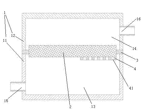
[0024] Embodiment one, see figure 1 , a split-type vehicle air filter, comprising a housing 1 and a filter element 2.
[0025] The housing 1 includes a lower case 11 and an upper case 12 . A filter cartridge holder 3 is sandwiched between the lower case 11 and the upper case 12 . Filter element 2 is installed on the filter element holder 3. The filter element 2 divides the inner space of the housing 1 into an air inlet chamber 13 and an air outlet chamber 14 . The left end of the air intake chamber 13 is provided with an air inlet 15 . The right end of the air outlet chamber 14 is provided with an air outlet 16 .
[0026] A splitter plate 4 is placed on the lower surface of the filter element 2 . Splitter plate 4 is fixed together with filter cartridge frame 3. The splitter plate 4 is located at the right end of the filter element 2 . The splitter plate 4 is provided with grid holes 41 .
[0027]During use, the air outlet 16 is connected with the intake port of the eng...
Embodiment 2
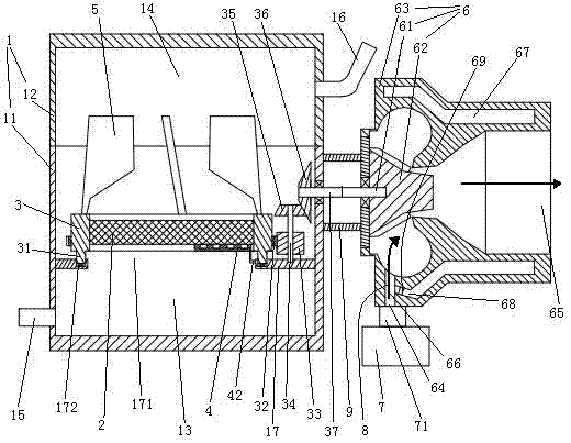
[0028] Embodiment two, see figure 2 , the difference from the first embodiment is: the inner surface of the lower casing 11 is provided with a support plate 17 with a through hole 171 . A circular turning groove 172 is formed on the upper surface of the support plate 17 . The filter holder 3 is located inside the casing 1 . A circular rotating ring 31 is provided on the lower end surface of the filter cartridge holder 3 . The rotating ring 31 is sealingly inserted into the rotating groove 172 . The filter element 2 is located in the area surrounded by the rotating ring 31 . The splitter plate 4 is connected with the supporting plate 17 through the connecting frame 42 . A booster vane 5 is arranged on the upper end of the filter cartridge holder 3 . The booster vane 5 is located in the air outlet chamber 14 . A ring gear 32 is also provided on the side of the filter cartridge holder 3 . The ring gear 32 is an external ring gear. The ring gear 32 is coaxial with the rot...
Embodiment 3
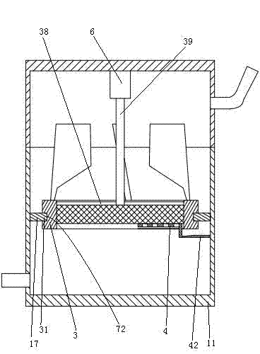
[0033] Embodiment three, see image 3 , the difference from the second embodiment is: the splitter plate 4 is directly fixed on the inner surface of the lower chamber 11 through the connecting frame 42 . The rotating ring 31 is provided on the inner peripheral surface of the connecting plate 17 . The rotating groove 172 is arranged on the outer surface of the filter cartridge holder 3 . The power device 6 is a DC motor. The filter core holder 3 is fixed on the motor output shaft 39 through connecting spokes 38 . During the working process, the vehicle battery is used to supply power to the power equipment, and the motor output shaft 39 drives the filter holder 3 to rotate through the connecting spokes 38 .
PUM
 Abstract
Description
Claims
Application Information
 - R&D
- Intellectual Property
- Life Sciences
- Materials
- Tech Scout
- Unparalleled Data Quality
- Higher Quality Content
- 60% Fewer Hallucinations
Browse by: Latest US Patents, China's latest patents, Technical Efficacy Thesaurus, Application Domain, Technology Topic, Popular Technical Reports.
© 2025 PatSnap. All rights reserved.Legal|Privacy policy|Modern Slavery Act Transparency Statement|Sitemap|About US| Contact US: help@patsnap.com


