
Drinking water storage tank

A technology for drinking water and water storage tanks, which is applied in the fields of water conservation, water/sewage treatment, water/sludge/sewage treatment, etc. The effect of preventing water pollution, ensuring drinking safety and good use effect

Inactive Publication Date: 2013-07-10
李英杰
View PDF8 Cites 2 Cited by
  • Summary
  • Abstract
  • Description
  • Claims
  • Application Information

AI Technical Summary

Problems solved by technology

[0002] At present, in the frequency conversion water supply equipment of the water tank, the water tank is not a fully enclosed structure, and it is easily polluted by the outside world, which brings people unhealthy water quality and affects the body.
At the same time, due to the fact that some dead angles are likely to appear when the water tank is square, it is easy to have problems such as stagnant water in the water tank, which affects the quality of the water.
Before the water tank used in ordinary water tanks or frequency conversion water supply equipment is connected to the water pump, a stabilizing tank needs to be installed to ensure the stability of the water flow and reduce the pressure, which will bring part of the design cost to the design of the water tank
The water tank needs a lot of manpower, material resources and financial resources every year in cleaning, and at the same time, a lot of water resources will be wasted in the cleaning process. In this way, it is a kind of waste in itself.
[0003] At present, in the differential compensation or non-negative pressure equipment, not only the water tank exists, but also the pipeline installation is very complicated
It can be said that the differential compensation water supply equipment is technically obsolete, as long as there is a water tank, the water quality will be polluted
[0004] In the above-mentioned water supply equipment, there is still a problem that has attracted more attention, that is, a certain amount of noise pollution is caused when water is injected into the water tank.

Method used


Image

  • Drinking water storage tank
  • Drinking water storage tank
  • Drinking water storage tank

Examples


Embodiment 1

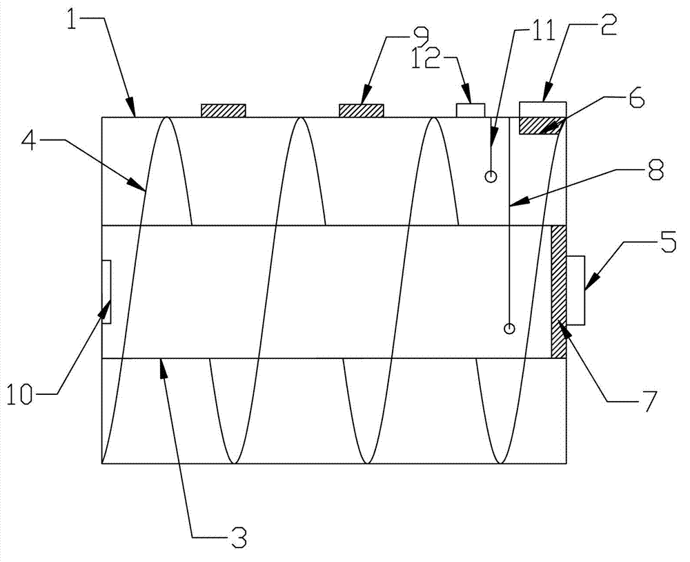
[0026] Embodiment 1: as figure 1 shown

[0027] The drinking water storage tank described in the embodiment of the present invention includes inner and outer tank bodies provided with a communication port 10, and a surrounding tank is provided in the space surrounded by the outer wall of the inner tank body 3 and the inner wall of the outer tank body 1. The diversion and noise-removing spiral plate 4 of the inner tank body, the inner and outer edges of the spiral plate are respectively connected with the outer wall of the inner tank body and the inner wall of the outer tank body; a water inlet is provided on the outer tank body 2. A water outlet 5 is provided on the inner tank body. In addition, a circle of deflector spiral plates can also be arranged in the inner tank body. The present invention erects the spiral plate in the tank body, and when the water storage tank is filled with water, the water flow flows along the spiral plate, reducing certain noise pollution. The no...

Embodiment 2

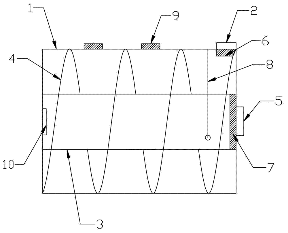
[0033] Embodiment 2: as figure 2 shown

[0034] The drinking water storage tank described in the embodiment of the present invention includes inner and outer tank bodies provided with a communication port 10, and a surrounding tank is provided in the space surrounded by the outer wall of the inner tank body 3 and the inner wall of the outer tank body 1. The diversion and noise-removing spiral plate 4 of the inner tank body, the inner and outer edges of the spiral plate are respectively connected with the outer wall of the inner tank body and the inner wall of the outer tank body; a water inlet is provided on the outer tank body 2. A water outlet 5 is provided on the inner tank body. In addition, a circle of deflector spiral plates can also be arranged in the inner tank body. The present invention erects the spiral plate in the tank body, and when the water storage tank is filled with water, the water flow flows along the spiral plate, reducing certain noise pollution. The n...

Embodiment 3

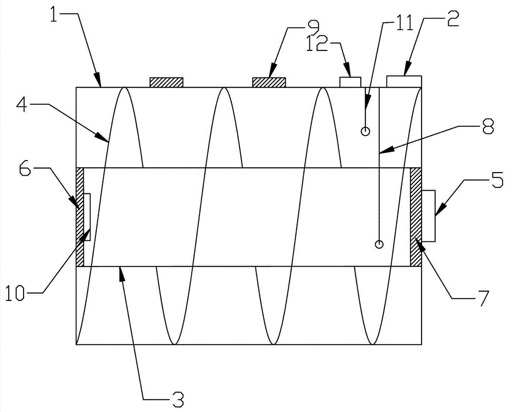
[0040] Embodiment 3: as image 3 shown

[0041] The drinking water storage tank described in the embodiment of the present invention includes inner and outer tank bodies provided with a communication port 10, and a surrounding tank is provided in the space surrounded by the outer wall of the inner tank body 3 and the inner wall of the outer tank body 1. The diversion and noise-removing spiral plate 4 of the inner tank body, the inner and outer edges of the spiral plate are respectively connected with the outer wall of the inner tank body and the inner wall of the outer tank body; a water inlet is provided on the outer tank body 2. A water outlet 5 is provided on the inner tank body. In addition, a circle of deflector spiral plates can also be arranged in the inner tank body. The present invention erects the spiral plate in the tank body, and when the water storage tank is filled with water, the water flow flows along the spiral plate, reducing certain noise pollution. The no...


PUM


Abstract

The invention discloses a drinking water storage tank, which realizes the purposes of pollution prevention, filtering and water purification. The drinking water storage tank comprises an inner tank body and an outer tank body which are respectively provided with a communication port; a flow guide noise elimination spiral plate surrounding the inner tank body is arranged in a space formed by the outer wall of the inner tank body and the inner wall of the outer tank body; the inner edge and the outer edge of the spiral plate are respectively connected with the outer wall of the inner tank body and the inner wall of the outer tank body; and a water inlet is formed in the outer tank body, and a water outlet is formed in the inner tank body. The drinking water storage tank can substitute a mounted flow stabilizing tank required by a common water tank, and has good use effects on pollution prevention, filtering and water purification; and in addition, owing to the spiral plate arranged in the outer tank body, a certain noise pollution can be reduced during injecting water into the water storage tank.

Description

technical field [0001] The invention relates to a water supply device, in particular to a drinking water storage tank. Background technique [0002] In the current water tank frequency conversion water supply equipment, the water tank is not a fully enclosed structure, which is easily polluted by the outside world, bringing unhealthy water quality to people and affecting the body. Simultaneously, because some dead angles are prone to appear when the water tank is square, cause problems such as dead water to be easy to occur in the water tank, affect the quality of water. Before the water tank used in ordinary water tanks or frequency conversion water supply equipment is connected to the water pump, a stabilizing tank needs to be installed to ensure the stability of the water flow and reduce the pressure, which will bring part of the design cost to the design of the water tank. The water tank needs a lot of manpower, material resources and financial resources every year for ...

Claims


Application Information

Patent Timeline
IPC IPC(8): E03B11/02C02F1/00
CPCY02A20/00Y02A20/152
Inventor 李英杰
Owner 李英杰
Learn More