
Osteopathy robot remote control system

A remote control system and robot technology, applied in surgical robots, medical science, surgery, etc., can solve problems such as the inability to realize remote control of osteopathic robots

Inactive Publication Date: 2013-07-10
哈尔滨首创骨科微创医疗设备有限公司
View PDF7 Cites 1 Cited by
  • Summary
  • Abstract
  • Description
  • Claims
  • Application Information

AI Technical Summary

Problems solved by technology

[0005] The present invention aims to solve the problem that the remote control of the osteopathic robot cannot be realized at present, thereby providing a remote control system of the osteopathic robot

Method used


Image

  • Osteopathy robot remote control system
  • Osteopathy robot remote control system

Examples


specific Embodiment approach 1

[0017] Specific implementation mode 1. Combination figure 2 Describe this specific embodiment, the osteopathic robot remote control system, it comprises operating room control unit 2, and described operating room control unit 2 comprises C-arm X-ray machine 25 and executive motor unit 29, and described executive motor unit 29 includes N Executing motors, said N is a positive integer;

[0018] The osteopathic robot control system also includes a remote monitoring unit 1, the remote control unit 1 includes an operating computer 12 and a dual-screen display 11; the display signal input end of the dual-screen display 11 is connected to the display signal output end of the operating computer 12; The operation computer 12 accesses the wireless network;

[0019] The control unit 2 in the operating room also includes a No. 1 camera 21, a No. 2 camera 22, an execution control computer 23, a voice output input system 24, a video acquisition card 26, a motor multi-axis controller 27 an...

specific Embodiment approach 2

[0028] Embodiment 2. The difference between this embodiment and the osteopathic robot remote control system described in Embodiment 1 is that it also includes a power supply system (30), the power signal output terminal of the power supply system (30) and the motor driver (28) is connected to the power signal input terminal.

[0029] The invention adopts an independent power supply system to provide uninterrupted power supply for the motor driver to ensure the uninterrupted use of the motor driver.

specific Embodiment approach 3

[0030] Embodiment 3. The difference between this embodiment and the osteopathic robot remote control system described in Embodiment 1 or 2 is that it also includes a PCI-E bus, and the video acquisition signal output end of the video acquisition card 26 is connected through PCI The -E bus is connected with the video acquisition signal input end of the execution control computer 23 .


PUM


Abstract

The invention discloses an osteopathy robot remote control system which relates to a robot remote control system, and aims at solving the problem that remote control on an osteopathy robot cannot be realized currently. The remote control system comprises a remote monitoring unit and a control unit in an operating room; the display signal input end of a double-screen display is connected with the display signal output end of an operating computer; the pickup signal input ends of two cameras are respectively connected with the two pickup signal input ends of an execution control computer; a video capture card captures video signals of a C-type arm X-ray machine and outputs the video signals to the execution control computer; the motor multi-shaft control signal output or input end of the execution control computer is connected with the motor multi-shaft control signal input or output end of a motor multi-shaft controller; and the motor driving signal input or output end of the motor multi-shaft controller is connected with the motor driving signal output or input end of a motor driver; and the motor driver is used for driving each motor in an execution motor set to work. The osteopathy robot remote control system is applicable to remote control on a osteopathy robot.

Description

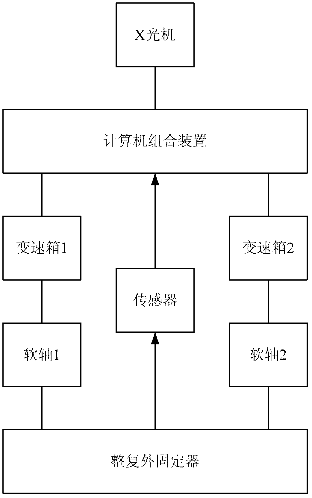
technical field [0001] The invention relates to a robot remote control system. Background technique [0002] Using orthopedic robots for intelligent orthopedic surgery operation and process monitoring is the most advanced mode at present. The operator can realize such as judging and correcting the fracture position, and can also directly control the start / stop of the C-arm X-ray machine on site. [0003] Publication No. CN1389182A "Computer Controlled Fracture Rehabilitation and Fixation System" discloses a control system for fracture reduction and fixation system, its structure is as follows: figure 1 As shown, it achieves the integration of optics, machinery and electronics, reduces the labor intensity of doctors, enables doctors to avoid X-ray damage, and improves the speed of bone setting accuracy. [0004] However, this control system can only realize on-site control of the osteopathic robot in the operating room, but cannot realize remote control of the osteopathic ro...

Claims


Application Information

Patent Timeline
IPC IPC(8): A61B19/00A61B34/30
Inventor 姜宁姜同参
Owner 哈尔滨首创骨科微创医疗设备有限公司
Learn More