Current sensor

A current sensor and current technology, which is applied in the direction of measuring current/voltage, instruments, measuring electrical variables, etc., can solve the problems of inability to measure the current correctly, difficult to measure the current value of the current circuit, etc.

Active Publication Date: 2013-07-03
ALPS ALPINE CO LTD
View PDF8 Cites 4 Cited by
  • Summary
  • Abstract
  • Description
  • Claims
  • Application Information

AI Technical Summary

Problems solved by technology

[0008] However, in the current sensor described above, when a disturbance magnetic field in a different direction is applied to the first Hall element for disturbance magnetic field detection and the second Hall element for current measurement, the current cannot be accurately measured.
In particular, when there is an adjacent current path arranged adjacent to the current path to be measured, it is difficult to accurately measure the current value of the current path to be measured due to the influence of the adjacent current path.

Method used


Image

  • Current sensor
  • Current sensor
  • Current sensor

Examples


Embodiment approach 1

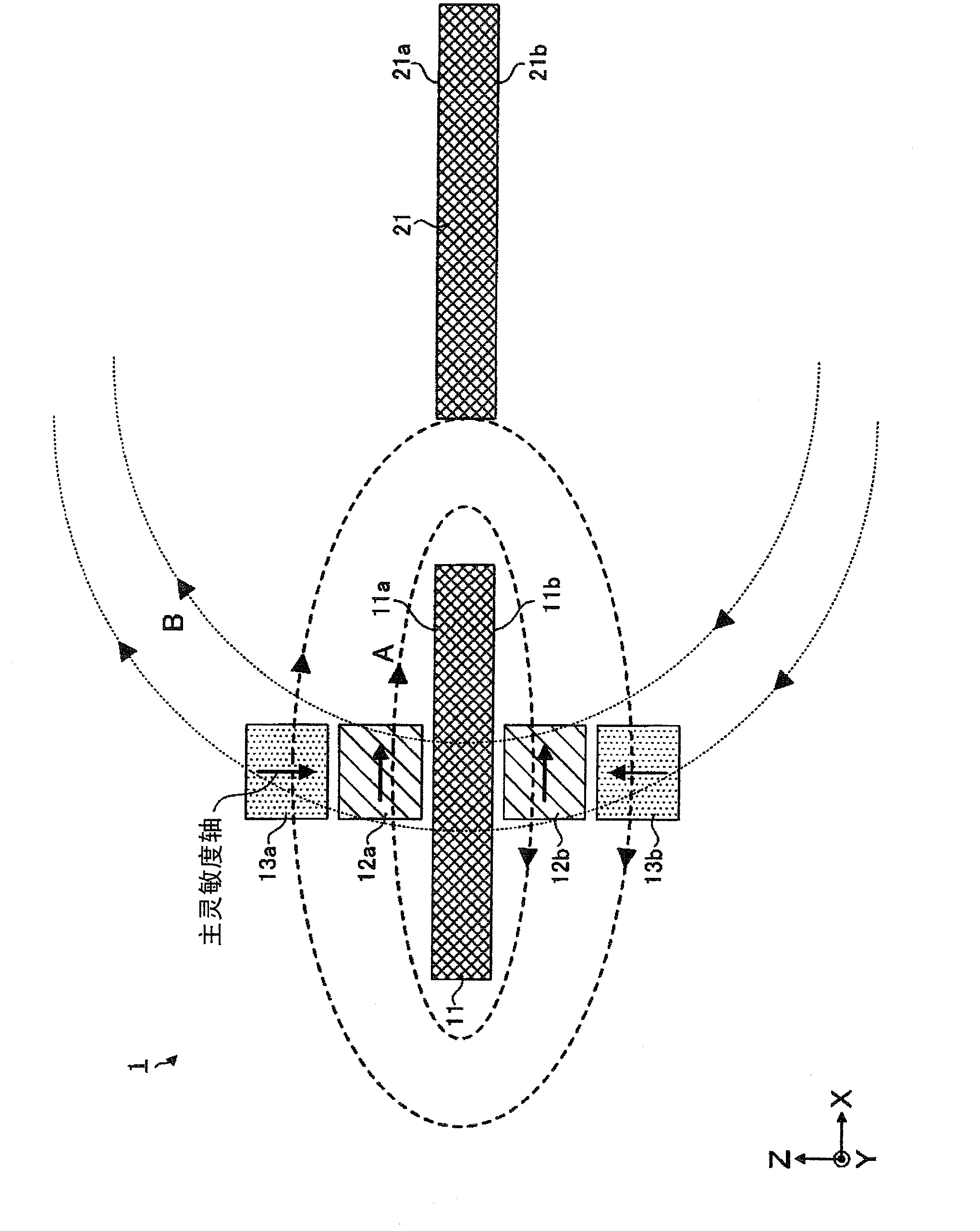
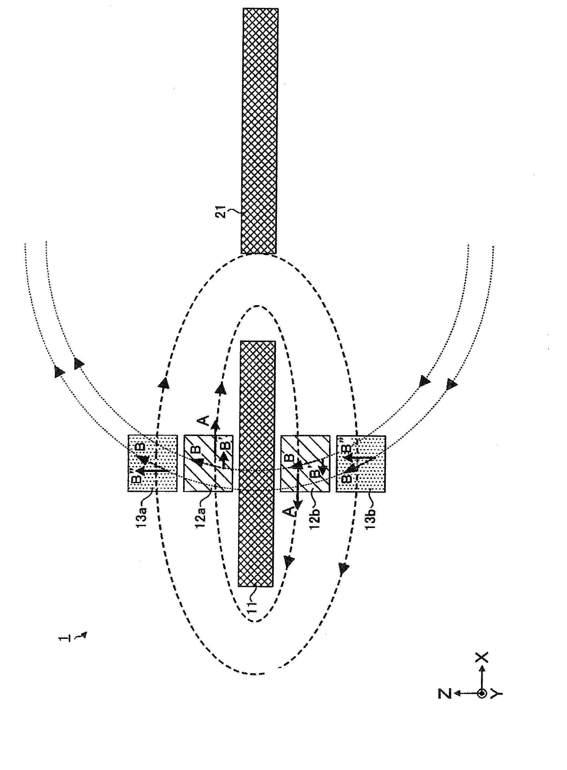
[0051] In this embodiment, refer to figure 1 An example of the current sensor of the present invention will be described. figure 1 is a schematic cross-sectional view of the current sensor 1 of the present embodiment. In addition, the schematic cross-sectional view of the current sensor corresponds to the case viewed from the direction in which the current to be measured flows (Y direction).

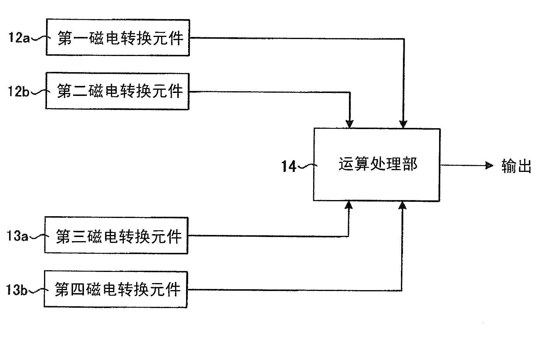
[0052] Such as figure 1 As shown, the current sensor 1 has: a measured current path 11; an adjacent current path 21, which is arranged adjacent to the measured current path 11; The generated magnetic field is measured; a pair of magnetoelectric conversion elements 13a, 13b for detecting the disturbance magnetic field selectively measure the magnetic field generated by the adjacent current.

[0053] The measured current path 11 and the adjacent current path 21 extend along any direction (in figure 1 Among them, a conductive member extending in the front-depth direction (Y direction) o...

Embodiment approach 2

[0077] In the magnetoelectric conversion element, there may be an axis affecting detection sensitivity (sensitivity influencing axis) in a direction perpendicular to the main sensitivity axis having the highest sensitivity. Among the directions perpendicular to the main sensitivity axis, the sensitivity influence axis includes the direction with the highest sensitivity (sub-sensitivity axis), and the direction in which a magnetic field is applied in the direction perpendicular to the main sensitivity axis in order to change the sensitivity (sensitivity change axis). ). For example, when a GMR element is used as the magnetoelectric conversion element, the sensitivity of the sub-sensitivity axis may reach about several tens% of the sensitivity of the main sensitivity axis. Therefore, in the current sensor, when using a magnetoelectric conversion element having a sub-sensitivity axis or the like in a direction perpendicular to the main sensitivity axis, it is preferable to also c...


PUM


Abstract

The invention provides a current sensor that may reduce the influence of a magnetic field generated by a current flowing in a neighboring current path which is provided in the vicinity of a current path to be measured, and accurately measure a current value of the current path to be measured. A current sensor includes the current path to be measured (11), a neighboring current path (21) that is provided in the vicinity of the current path (11) to be measured, first and second magnetoelectric transducers (12a, 12b) having a main sensitivity axis parallel to a direction of a magnetic field generated by a current to be measured flowing in the current path (11) to be measured, and are provided so that the directions of the magnetic fields generated by the current to be measured are applied in mutually opposite directions, and third and fourth magnetoelectric transducers (13a, 13b) having a main sensitivity axis being non-orthogonal to a direction of a magnetic field generated by the neighboring current while being orthogonal to the direction of the magnetic field generated by the current to be measured, and are provided so that the directions of the magnetic fields generated by the current to be measured are applied in mutually opposite directions.

Description

technical field [0001] The present invention relates to a current sensor for measuring a current flowing in a conductor without the influence of a disturbing magnetic field. Background technique [0002] In the field of motor drive technology for electric vehicles, hybrid vehicles, etc., in order to handle relatively large currents, current sensors capable of measuring the large currents in a non-contact manner are required. Such a current sensor is mounted on, for example, a three-phase motor or the like having three current paths arranged in parallel. In the current sensor mounted on such a three-phase motor, it is necessary to prevent the measurement accuracy of the current to be measured from deteriorating by suppressing the influence of the magnetic field generated by the adjacent current flowing in the adjacent current path arranged adjacent to the current path to be measured. [0003] As such a current sensor, there is proposed a current sensor that differentially pr...

Claims


Application Information

Patent Timeline
Patent Type & Authority Applications(China)
IPC IPC(8): G01R19/00
CPCG01R15/202G01R15/207G01R33/07
Inventor 田村学
Owner ALPS ALPINE CO LTD
Why Eureka
Try Eureka