
Flexible-drive transmission

A transmission, flexible technology, applied in the direction of transmission, gear transmission, belt/chain/gear, etc., can solve the problem that it is difficult to play the best working curve of the power source

Inactive Publication Date: 2013-07-03
崔莹泉
View PDF5 Cites 0 Cited by
  • Summary
  • Abstract
  • Description
  • Claims
  • Application Information

AI Technical Summary

Problems solved by technology

[0010] Mode 3 has problems such as the speed coordination between the two power sources is fixed, and it is difficult to play the best working curve of each power source.

Method used


Image

  • Flexible-drive transmission
  • Flexible-drive transmission
  • Flexible-drive transmission

Examples


Embodiment Construction

[0019] The implementation is described below with a specific example, and the actual implementation is not limited to this example.

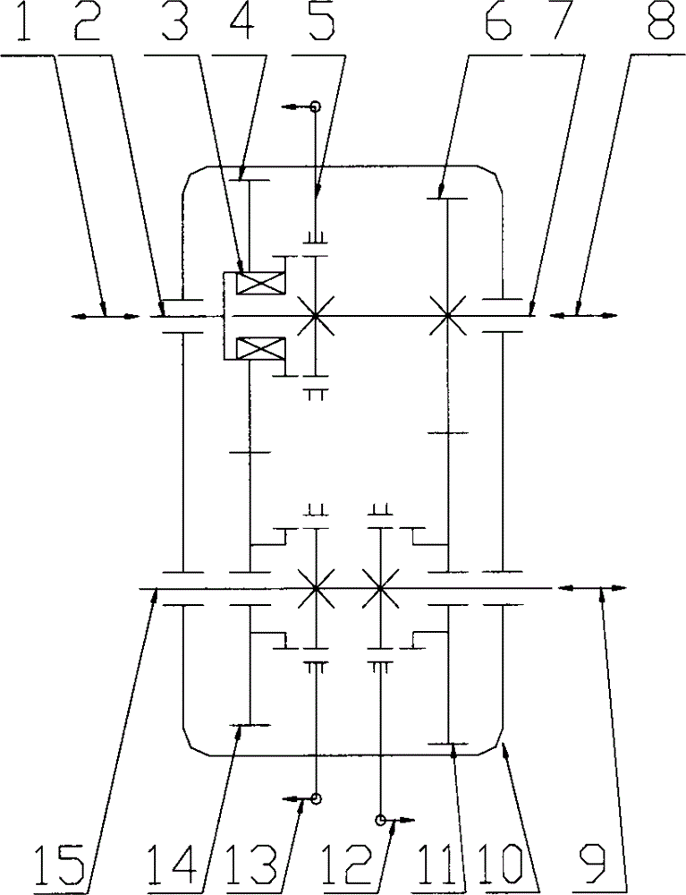
[0020] as attached figure 1 As shown, disconnect 5 clutch device A, 12 clutch device B, and 13 clutch device C, the system is in the "neutral" state, that is, all power transmission paths are in the disconnected state, and each power source or load can move freely.

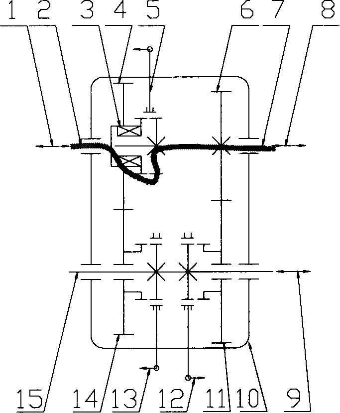
[0021] as attached figure 2 As shown, close 5 clutch devices A, open 12 clutch devices B, 13 clutch devices C, 1 power source or load A and 8 power sources or load B can transmit power at a speed ratio of 1, as shown in the thick solid line in the figure shown.

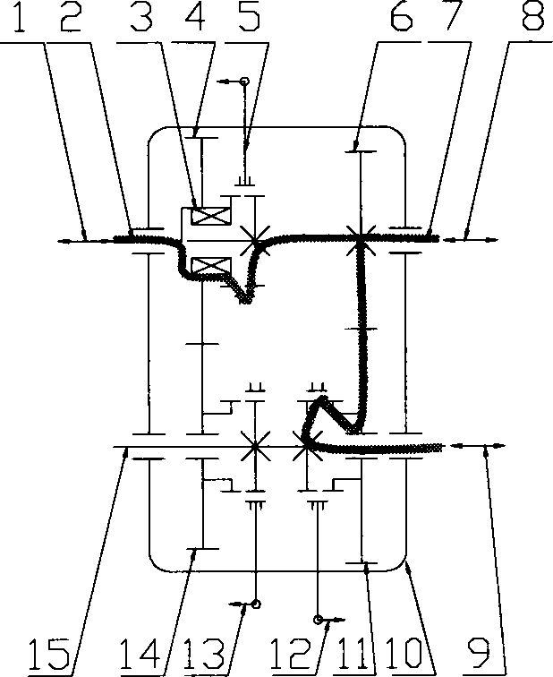
[0022] as attached image 3 As shown, close 5 clutches A, 12 clutches B, open 13 clutches C, 1 power source or load A, 8 power sources or load B and 9 power sources or load C can be driven by 6 gears or other transmissions The transmission ratio formed by device B, gear 11 or other transmission mechanism C transmits po...


PUM


Abstract

The invention discloses a flexible-drive transmission. The flexible-drive transmission comprises a shaft A 2, a bearing 3, a gear 4 or drive mechanisms A, a clutch device A 5, a gear 6 or drive mechanisms B, a shaft B 7, a shell 10, a gear 11 or drive mechanisms C, a clutch device B 12, a clutch device C 13, a gear 14 or drive mechanisms D and a shaft C 15, wherein the shaft A 2 and the shaft B 7 share an axial line and support each other through the bearing 3; and the clutch device A 5 is arranged between the shaft A 2 and the shaft B 7 and can connect or disconnect power transmission paths of the two shafts. Through reasonable operation of the clutch devices, power can be flexibly transmitted between multiple power sources or loads and the transmission paths can be switched under the condition that the power transmission is not interrupted; and the flexible-drive transmission has the advantages of simple structure, flexible transmission path and good succession to the conventional transmission case technology, and can be widely applied to automobiles, rail vehicles, ships, construction machinery, agricultural machinery and other power equipment.

Description

[technical field] [0001] The invention relates to a power transmission system, especially a gear reducer, a speed change device, a hybrid vehicle, a speed reducer and a transmission with three or more power sources and loads, and can be widely used in automobiles, rail vehicles, ships, engineering machinery, agricultural Machinery and other power equipment. [Background technique] [0002] At present, due to the pressure of energy conservation and emission reduction, vehicle energy conservation and emission reduction standards are becoming increasingly stringent. In order to reduce the energy consumption of vehicles, many new vehicle systems including electric vehicles and hybrid vehicles have been developed. Pure electric vehicles have the advantages of energy saving and environmental protection, and have gradually attracted the attention of major automobile manufacturers. An electric vehicle is a motor vehicle formed by replacing the engine with an electric motor on the b...

Claims


Application Information

Patent Timeline
IPC IPC(8): F16H3/085
Inventor 崔莹泉
Owner 崔莹泉
Learn More