Sliding gear type differential device

A technology for sliding gears and differentials, which is applied in differential transmissions, gear lubrication/cooling, belts/chains/gears, etc. It can solve problems such as poor steering flexibility, high prices, and impacts on teeth and cogs, and achieve transmission The effect of reliable driving torque, simple operation and flexible steering

Inactive Publication Date: 2013-02-27
HUNAN AGRICULTURAL UNIV
View PDF7 Cites 5 Cited by
  • Summary
  • Abstract
  • Description
  • Claims
  • Application Information

AI Technical Summary

Problems solved by technology

[0004] The present invention aims at the complex operation of the existing jaw clutch steering mechanism, the poor steering flexibility, the impact of the jaw gear, and the non-limited-slip differential used in automobiles that cannot meet the power transmission requirements after the differential speed of agricultural machinery. The limited-slip differential The structure is complex and expensive, and it is not suitable for agricultural machinery. A sliding gear differential is provided. The differential can ensure that at least one power output shaft is moving while differential, so that the drive can be reliably transmitted. Torque, the structure of the mechanism is simple, no need for separate operation, easy to use, and strong practicability

Method used


Image

  • Sliding gear type differential device
  • Sliding gear type differential device
  • Sliding gear type differential device

Examples


Embodiment Construction

[0024] Below in conjunction with accompanying drawing, the specific implementation manner of this patent is described in further detail.

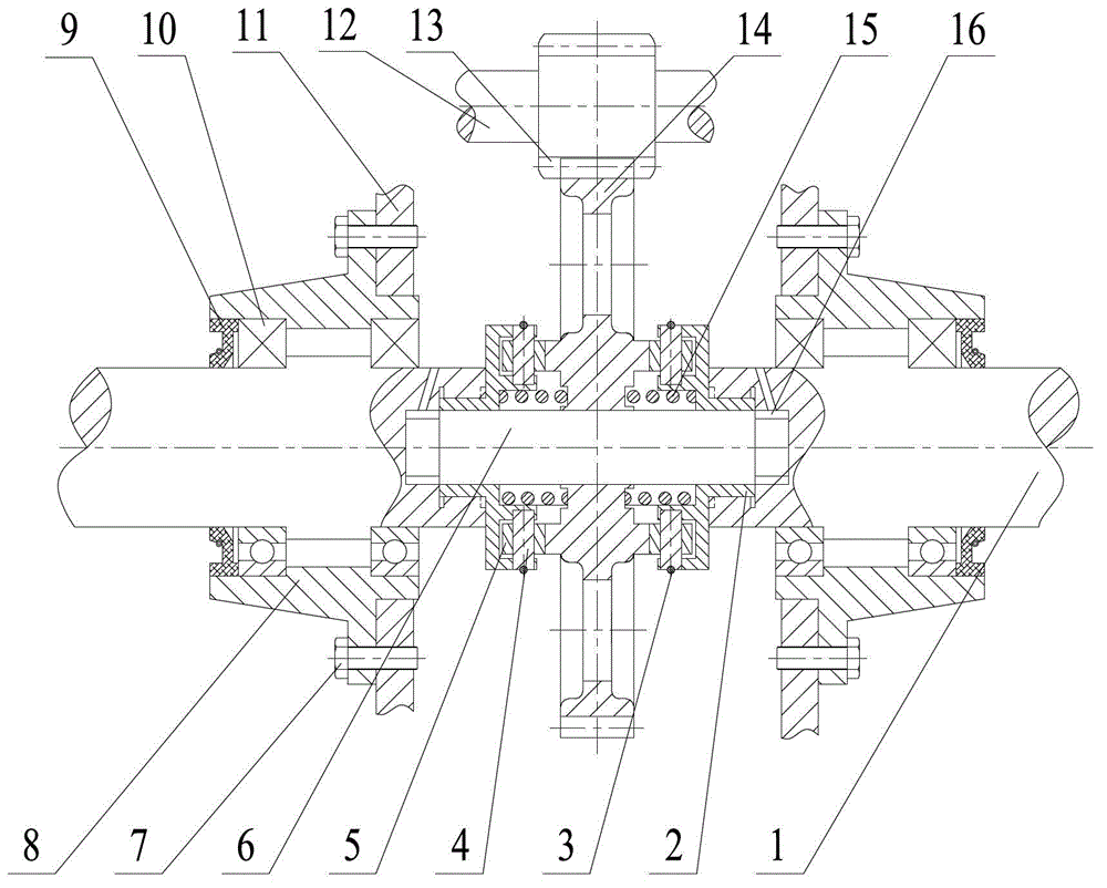
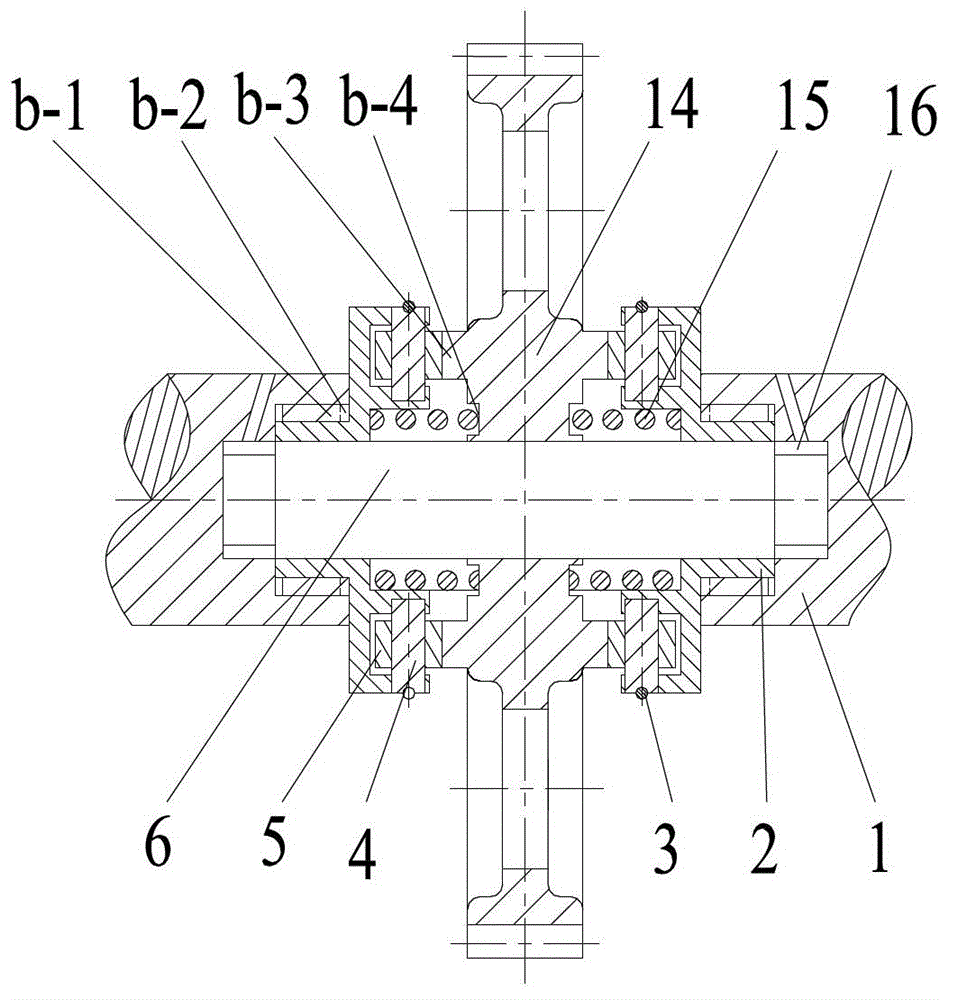
[0025] see figure 1 , a sliding gear differential, comprising a power output shaft 1, a roller frame 2, a roller shaft clamp 3, a roller shaft 4, a roller 5, a support shaft 6, bolts 7, an end cover 8, an oil seal 9, a bearing 10, Box 11, power input shaft 12, power input gear 13, sliding gear 14, spring 15, sliding sleeve 16;

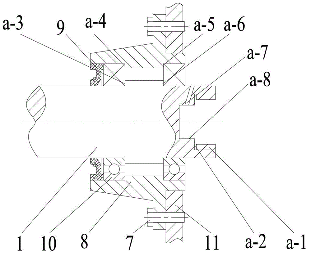
[0026] see figure 1 with figure 2 , the end cover 8 is fixed on the box body 11 through the bolt 7, the power output shaft 1 is positioned on the end cover 8 through the bearing 10, and the oil seal 9 is installed on the outer end of the end cover 8; the power output shaft 1 is designed with a step a -3 and a-6, its width is equal to the steps a-4 and a-5 on the end cover 8, one of the bearings 10 is installed on the steps a-3 and a-4, and the other is installed on the steps a-5 and the steps At a-6, this struc...


PUM


Abstract

The invention relates to a sliding gear type differential device which comprises a sliding gear, rollers, roller shafts, roller frames, springs, roller shaft hoops, a supporting shaft and a power output shaft. The supporting shaft is positioned and supported through a round hole at the inner end of the power output shaft, the sliding gear is installed on the supporting shaft, the rollers are installed on the roller frames through the roller shafts to form a roller transmission assembly, and the roller transmission assembly and the sliding gear are symmetrically arranged; and bosses are evenly distributed at two ends of the sliding gear along the peripheral direction, and the rollers are installed at half positions of grooves of the bosses. When resisting moments at two ends of the power output shaft are same, the sliding gear is located between the two roller frames, and the power output shaft rotates along a same direction in a constant speed; when the resisting moments at two ends of the power output shaft are different, the sliding gear moves toward one end which has small moments, the end with the small moments drives rotation speeds to accelerate, and the rotation speeds at the end with the large moments are reduced; and when the resisting moments at two ends of the power output shaft differ in a certain range, power of the end with the large moments is interrupted, and the end with the small moments keep transmission of power so as to achieve speed differential.

Description

technical field [0001] The invention belongs to a differential for agricultural machinery transmissions, in particular to a sliding gear differential. Background technique [0002] When the car is running, the distance traveled by the left and right wheels at the same time is usually different. If the left and right wheels of the driving axle are rigidly connected, the driving wheels will inevitably slip or slip on the road when driving, which will not only aggravate the tire Wear and power and fuel consumption, and may lead to deterioration of steering and handling performance, so in order to prevent these phenomena, the car is equipped with an inter-wheel differential between the left and right wheels. However, when the car is driving off-road or on muddy, icy and snowy roads, the adhesion coefficient between the driving wheel on one side and the ground is very small, although the other wheel has good adhesion to the ground, its driving torque will also decrease accordingl...

Claims


Application Information

Patent Timeline
IPC IPC(8): F16H48/12F16H48/38F16H57/04
Inventor 肖名涛孙松林蒋蘋谢方平吴畏李军政杨彪
Owner HUNAN AGRICULTURAL UNIV
Why Eureka
Try Eureka