
thin fan

A thin fan and fan frame technology, which is applied to parts of pumping devices for elastic fluids, non-variable pumps, machines/engines, etc., can solve the problems of low heat dissipation efficiency, overall height reduction, and bearing system height reduction and other issues to achieve the best heat dissipation performance, enhanced stability, and long life conditions

Inactive Publication Date: 2016-11-23
FURUI PRECISE COMPONENT (KUNSHAN) CO LTD +1
View PDF6 Cites 1 Cited by
  • Summary
  • Abstract
  • Description
  • Claims
  • Application Information

AI Technical Summary

Problems solved by technology

Due to the narrowing of the internal space of the computer and the gap between the upper and lower air intakes of the thin fan, the thickness of the traditional thin fan is severely compressed, and the air flow is not high, resulting in low heat dissipation efficiency; moreover, the traditional thin fan becomes thinner Afterwards, its overall height is reduced, thereby reducing the height of the bearing system, reducing the oil storage capacity of the bearing, and reducing the supporting force of the bearing, which greatly affects the service life of the thin fan

Method used


Image

  • thin fan
  • thin fan
  • thin fan

Examples


Embodiment Construction

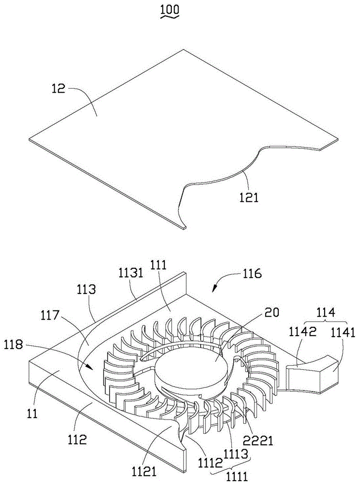
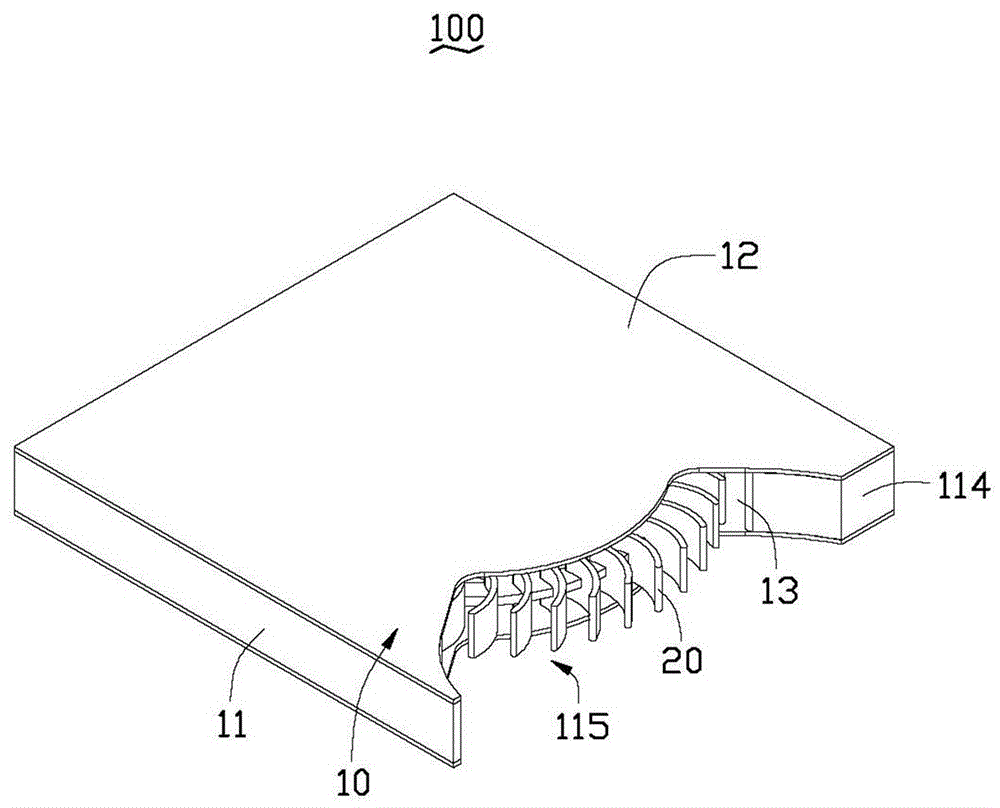
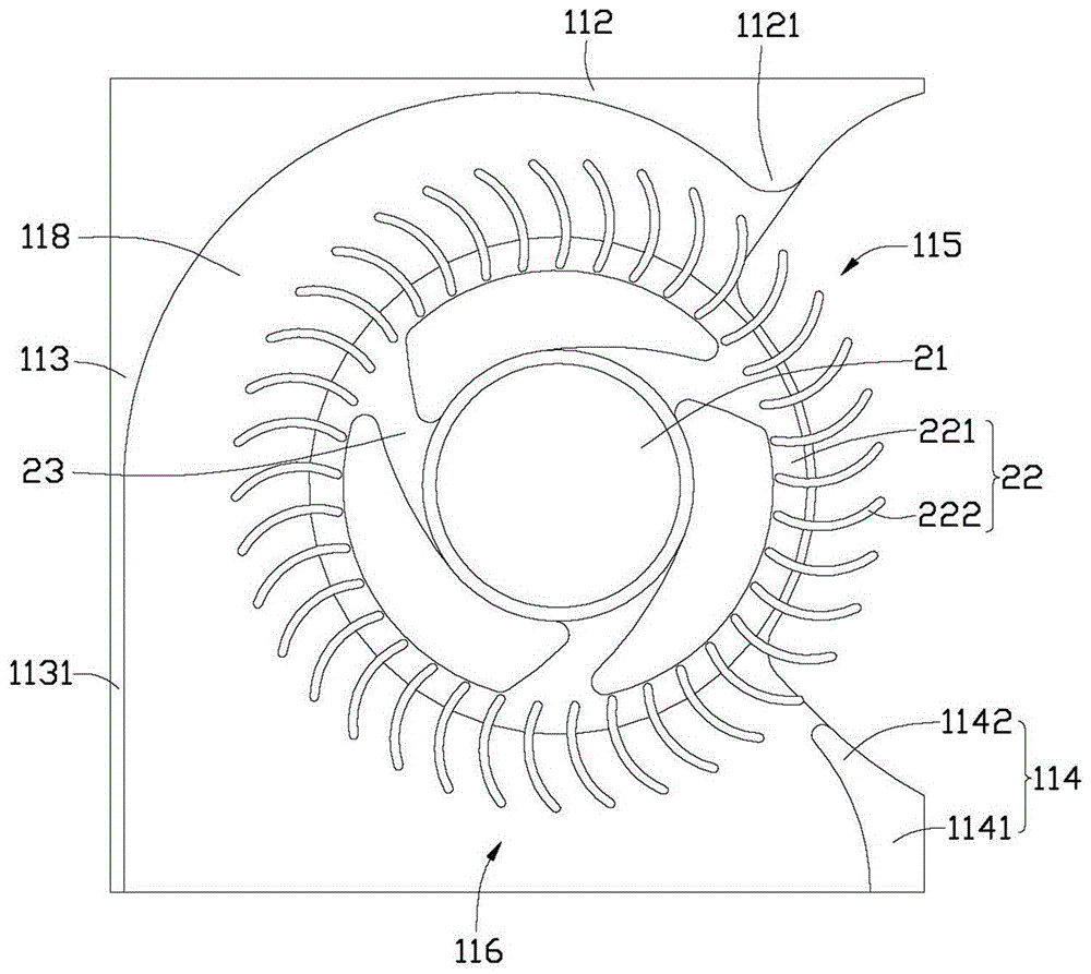
[0018] see Figure 1 to Figure 3 , which is the thin fan 100 according to the first embodiment of the present invention, which includes a fan frame 10 and an impeller 20 accommodated in the fan frame 10 . The thin fan 100 can be clipped and fixed on a related electronic device (not shown) to assist the electronic device to dissipate heat.

[0019] Specifically, see figure 1 The fan frame 10 includes a fan base 11 and an upper cover 12 located on the fan base 11 . The fan base 11 and the upper cover 12 form an accommodation space 13 for accommodating the impeller 20 . The fan base 11 includes a bottom plate 111 , a first side wall 112 , a second side wall 113 and a third side wall 114 opposite to the second side wall 113 extending upward from the edge of the bottom plate 111 . The bottom plate 111 is in the shape of a square plate, and its edge adjacent to the third side wall 114 is recessed inward to form a first recess 1111 . The groove 1112 and an arc-shaped protrusion 11...


PUM


Abstract

A thin fan, comprising an impeller and a fan frame for accommodating the impeller, an air outlet is opened on a side wall of the fan frame, and an air inlet is provided on the side wall of the fan frame. on the other side wall adjacent to the side wall. Compared with the prior art, the present invention adopts the structure of side air inlet and side air outlet to place the thin fan at a suitable position, and there is no need to reserve air intake space between the impeller of the thin fan, the upper cover and the bottom plate. Such a design makes full use of the accommodation space formed by the upper cover and the fan seat, thereby increasing the air flow of the entire thin fan. Based on the application of the thin fan, the present invention can provide a higher bearing system, which can ensure the oil storage capacity of the bearing system, and has a higher life condition than the traditional fan. In addition, the higher bearing system has a stronger supporting capacity and can enhance The stability of the whole thin fan ensures the best heat dissipation performance of the whole thin fan.

Description

technical field [0001] The invention relates to a fan device, in particular to a thin fan used for heat dissipation of electronic products. Background technique [0002] With the increasing performance of electronic products, a large amount of heat is also generated. A cooling fan is a component that is often used to assist heat dissipation. [0003] On the other hand, electronic products tend to be smaller in size, lighter in weight, and thinner in thickness, such as notebook computers. In order to meet the needs of thin electronic products, fans must also develop towards thinness. [0004] A traditional thin fan generally includes a fan frame and an impeller housed in the fan frame. The fan frame includes an upper cover, a lower cover and a side wall connecting the upper cover and the lower cover, and the upper cover and the lower cover are provided with air inlets. , an air outlet is provided on one side of the side wall. Under the thin structure with limited space, h...

Claims


Application Information

Patent Timeline
Patent Type & Authority Patents(China)
IPC IPC(8): F04D29/42F04D29/28
CPCF04D17/04F04D25/0613F04D29/4226F05D2250/51
Inventor 刘智仁许佑玮
Owner FURUI PRECISE COMPONENT (KUNSHAN) CO LTD
Learn More