Ear thermometer
A thermometer and ear-type technology, applied in radiation pyrometry, sensors, diagnosis, etc., can solve problems such as inability to detect properly, large measurement errors, and inability to ensure measurement status
- Summary
- Abstract
- Description
- Claims
- Application Information
AI Technical Summary
Problems solved by technology
Method used
Image


Examples
no. 1 Embodiment approach
[0034]
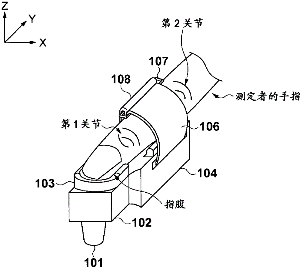
[0035] First, the external appearance structure of the ear thermometer 100 of the first embodiment of the present invention will be described. figure 1 It is a figure which shows the external appearance structure of the ear thermometer 100 of the 1st Embodiment of this invention.
[0036] in figure 1 Here, 101 is a probe part, which is inserted into the ear cavity (external auditory meatus) in order to detect infrared rays radiated from the temperature measurement site in the ear cavity (preferably the tympanic membrane and / or its periphery). The probe part 101 has a cylindrical shape with an outer diameter of about 7 mm at the tip, so that it can be inserted into the ear cavity.
[0037] 102 is a probe support part, and the probe part 101 is supported on one surface. In addition, a finger fixing wall 103 is provided on the surface 111 opposite to the surface supporting the probe portion 101, and the finger fixing wall 103 defines the X-axis direction of the finger when ...
no. 2 Embodiment approach
[0090] In the above-mentioned first embodiment, the structure in which the ear thermometer 100 is attached to the finger of the examiner using the attaching parts (102 and 104) and the attaching straps 106, 108 is adopted, but the present invention is not limited to this, for example, It may be a structure for installation through a finger-type installation part. In addition, in the first embodiment described above, when the ear thermometer 100 is installed, the probe support portion 102 and the fixing portion 104 are located on the same side (that is, the probe portion 101 and the fixing portion 104 are located on the same side), but the present invention does not Limited to this, for example, the probe part and the fixing part may be arranged on different sides. Hereinafter, an ear-type thermometer having a finger-cuff type attachment part and arranged so that the probe part and the fixing part are located on opposite sides during attachment will be described.
[0091]
[0092...
no. 3 Embodiment approach
[0118] In the first and second embodiments described above, the measurement start switch 203 (or 823) is arranged on the side surface of the fixed portion 104 (or the main body portion 803). However, when the subject is an infant or the like, when the body temperature is measured, fingers other than the finger on which the ear thermometer 100 or 800 is attached are used to hold the subject. Therefore, in a state where the probe section 101 (or 801) is inserted into the ear cavity, it is not always easy to press the measurement start switch 203 (or 823).
[0119] Therefore, in the ear thermometer of the present embodiment (referred to as ear thermometer 1200), when the probe portion is reliably inserted into the ear cavity, it is configured to detect this and automatically start the measurement. Hereinafter, the details of this embodiment will be described.
[0120]
[0121] First, the structure of the probe section 1201 of the ear thermometer 1200 will be described. Picture 12 It...
PUM
 Abstract
Description
Claims
Application Information
 - R&D
- Intellectual Property
- Life Sciences
- Materials
- Tech Scout
- Unparalleled Data Quality
- Higher Quality Content
- 60% Fewer Hallucinations
Browse by: Latest US Patents, China's latest patents, Technical Efficacy Thesaurus, Application Domain, Technology Topic, Popular Technical Reports.
© 2025 PatSnap. All rights reserved.Legal|Privacy policy|Modern Slavery Act Transparency Statement|Sitemap|About US| Contact US: help@patsnap.com