
Weak electromagnetic coupling path determining method

An electromagnetic coupling and determination method technology, applied in the direction of measuring electricity, measuring electrical variables, measuring devices, etc., can solve problems such as poor pertinence, time-consuming and labor-intensive problems, achieve low cost, effective electromagnetic compatibility problems, and solve electromagnetic compatibility problems Effect

Active Publication Date: 2013-06-26
BEIHANG UNIV
View PDF3 Cites 4 Cited by
  • Summary
  • Abstract
  • Description
  • Claims
  • Application Information

AI Technical Summary

Problems solved by technology

[0005] The present invention solves the problem of not strong pertinence, time-consuming and labor-intensive point-by-point investigation by relying on experience in the past by adopting the method of optimizing the minimum path of the directed graph. According to the method, the content of finding the weak coupling path includes the following steps:

Method used


Image

  • Weak electromagnetic coupling path determining method
  • Weak electromagnetic coupling path determining method
  • Weak electromagnetic coupling path determining method

Examples


Embodiment

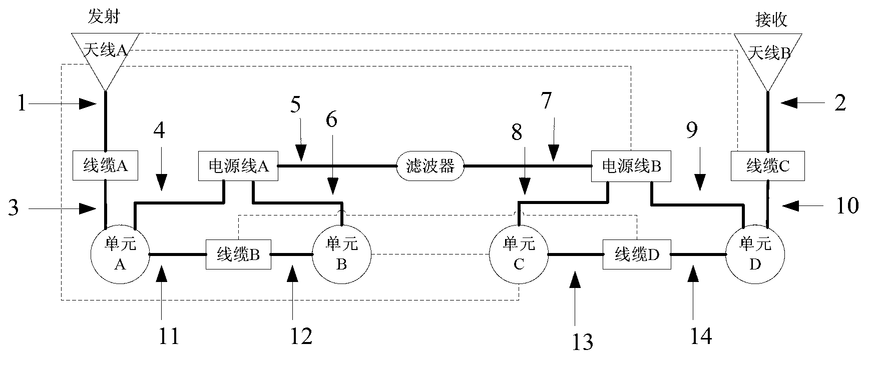
[0051] In an electronic system composed of a radio station and a processor, it was found that the radio station was interfered at a certain frequency point, resulting in strong noise in the earphones, which was unbearable for the operator. Through analysis, the fault source is located in a certain processor. The working principle of the electronic system is shown in the Figure 5 shown.

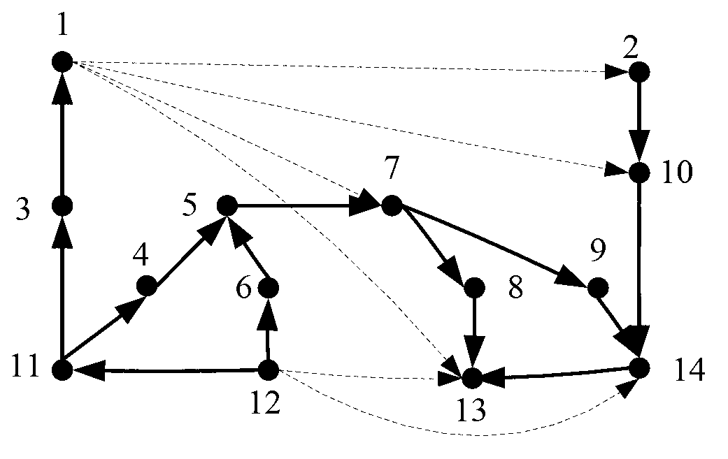
[0052] Since the radiation frequency of antenna A and antenna B is above 1 GHz, which is much higher than the receiving frequency band of antenna C, the influence of antenna A and antenna B on antenna C is ignored. By analyzing the possible interference link of the processor interfering with the radio station, the interference coupling network between the processor and the radio station can be obtained, such as Figure 6 shown. The electromagnetic interference coupling network between the processor and the radio station mainly includes the following paths:

[0053] 1) The processor enters...


PUM


Abstract

The invention discloses a weak electromagnetic coupling path determining method and belongs to the technical field of electromagnetic compatibility. The method includes: converting a schematic diagram of equipment into an electromagnetic interference coupling network, converting the coupling network into a coupling directed diagram, simplifying the coupling directed diagram, and finding out weak links of electromagnetic coupling paths in the coupling network by the shortest path tracing algorithm, so that problems of low pertinence, time consuming and labor consuming in previous electromagnetic compatibility troubleshooting of electronic systems are solved. In consideration of that primary coupling paths and secondary coupling paths exist in the electromagnetic coupling network, the shortest path tracing algorithm is adopted to find weak paths of electromagnetic interference coupling so as to accurately know main coupling processes of interference signals, so that the electromagnetic compatibility problem is rectified more specifically and effectively.

Description

technical field [0001] The invention belongs to the technical field of electromagnetic compatibility, and relates to a method for finding weak coupling paths of electromagnetic compatibility faults or hidden dangers, more precisely, a method for determining weak electromagnetic coupling paths of interference pairs at a single interference frequency point. Background technique [0002] In the cooperative work of multiple electronic devices, the electromagnetic interference generated by one device will be coupled to another device through conducted emission (CE) and radiated emission (RE), causing the performance of the other device to decline, or even malfunction Work. With the increasing precision and complexity of system equipment, the electromagnetic compatibility of the system has been widely concerned by people. [0003] There is a complex electromagnetic coupling relationship between interference equipment and sensitive equipment, and interference energy can affect sen...

Claims


Application Information

Patent Timeline
IPC IPC(8): G01R31/00
Inventor 贾云峰吴亮魏嘉利苏东林苏航马超武南开刘昌
Owner BEIHANG UNIV
Learn More