Power transmission device

A power transmission device and input shaft technology, applied in the direction of power devices, electric power devices, transmission parts, etc., can solve problems such as cavitation failure, oil pump pressure head drop, failure, etc., achieve simple structure and prevent cavitation failure Effect

Inactive Publication Date: 2013-06-19
AISIN SEIKI KK
View PDF1 Cites 24 Cited by
  • Summary
  • Abstract
  • Description
  • Claims
  • Application Information

AI Technical Summary

Problems solved by technology

Cavitation failure occurs when an oil pump sucks lubricating oil containing air bubbles and can lead to a drop in the pump head of the oil pump and failure in operation

Method used


Image

  • Power transmission device
  • Power transmission device
  • Power transmission device

Examples


Embodiment Construction

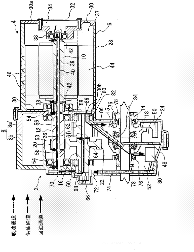
[0024] The following will refer to Figure 1 to Figure 3 An embodiment of the power transmission device 2 is explained. figure 1 Shown are the electric motor 4 and the power transmission device 2 that transmits the driving force generated by the electric motor 4 to the left and right wheels of the vehicle.

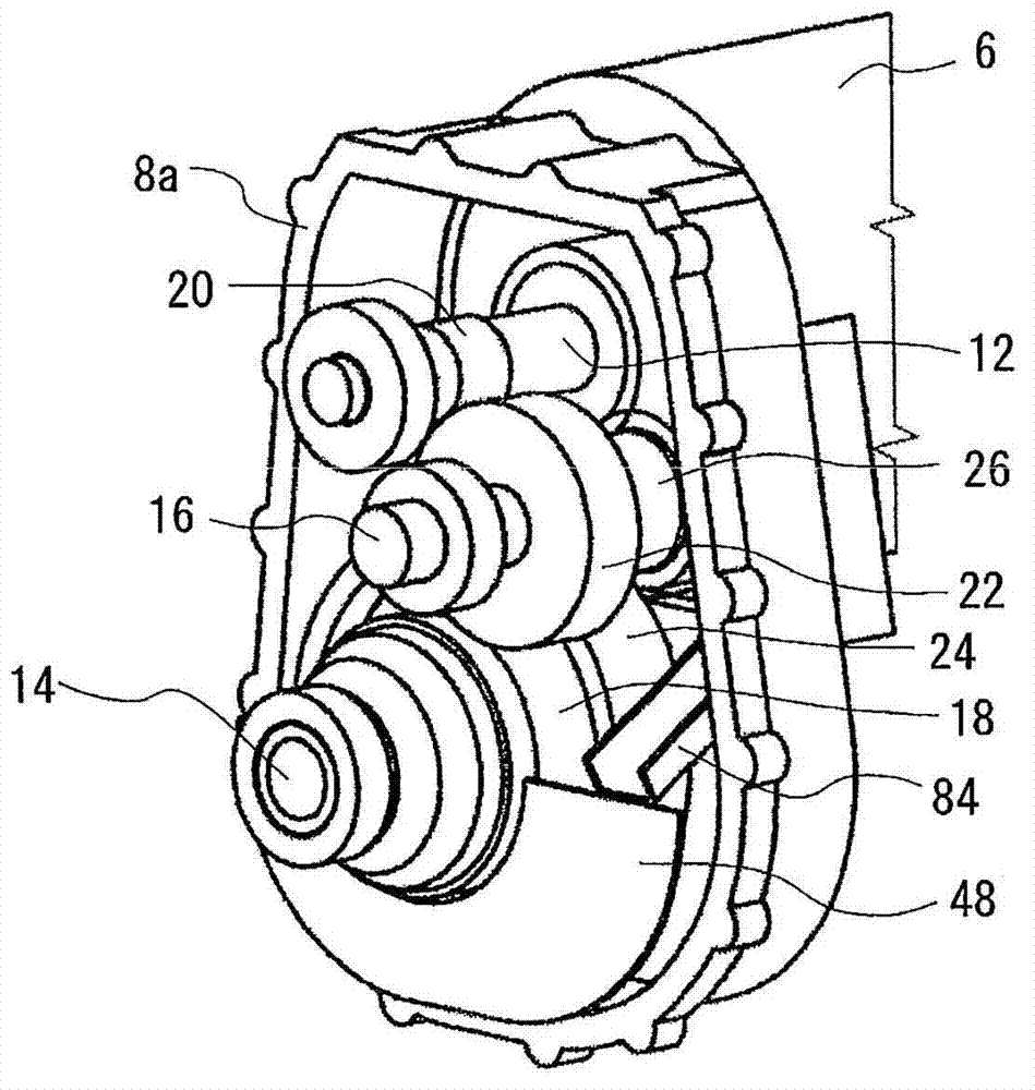
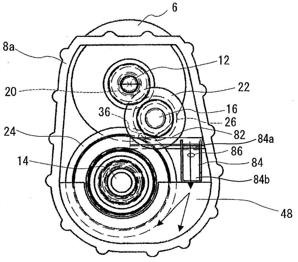
[0025] The power transmission device 2 mainly includes: an input shaft 12 connected to figure 1 The rotor shaft 10 of the electric motor (vehicle drive motor) 4 at the left end shown in ; the output shaft 14 , which is arranged parallel to the input shaft 12 ; One end of the motor casing (housing) 6 (in the figure 1 , corresponding to the connection part between the input shaft 12 and the output shaft 14 in the gear housing (housing) 8 at the left end). The motor case 6 and the gear case 8 serve as a case.

[0026] A differential gear 15 is formed on the periphery of the output shaft 14 . The differential gear 15 is housed in a gear case 18 pivotally supported on the ...


PUM


Abstract

Problem: Lubrication oil agitated by a final gear (e.g. ring gear of a differential) of a power transmission device includes bubbles which might result in cavitation failure of an oil pump. Solution: The oil reservoir is divided in a first (50) and a second (52) oil reservoir. The first oil reservoir (50) accomodates the final gear (24), the oil agitation of which causing bubbles. The second oil reservoir (52) does not accomodate the final gear and thus has no bubbles. The oil pump draws oil from the second oil reservoir (52) without bubbles. Thus, pump cavitation failure is prevented. Application: Electric drive of a vehicle axle having an electric motor, a reduction gear and a differential.

Description

technical field [0001] The present invention generally relates to a power transmission device. Background technique [0002] Lubricating oil must be delivered to facilitate lubrication between assembly parts included in a power transmission device that transmits The driving force used to drive the vehicle. [0003] As a known power transmission device, for example, a vertical power transmission device is disclosed in Patent Document JP2001-190042A (hereinafter referred to as Patent Document 1), which includes: an input shaft directly connected to the the rotor shaft; the output shaft, which is connected to the axle of the vehicle; and the countershaft (reduction mechanism), which is located between the input and output shafts in the gear housing. The input shaft is arranged at a higher position than the output shaft. The countershaft acts as an auxiliary shaft. These three shafts are provided with gears on the outer peripheries of the respective shafts for transmitting t...

Claims


Application Information

Patent Timeline
IPC IPC(8): F16H57/04F16H57/02
CPCF16H57/0423F16H57/043F16H57/0441F16H57/0453F16H57/0457F16H57/0471F16H57/0476F16H57/0483B60K2001/001Y10T74/19991F16H57/042
Inventor 中村忍野中典昭木村豪三上淳
Owner AISIN SEIKI KK
Why Eureka
Try Eureka