Follow-up guiding type annual guiding rail feeding device

A follow-up guided, ring-shaped guide rail technology, applied in the direction of conveyors, transportation and packaging, etc., can solve problems such as complex structure, inflexible application, and jamming

Inactive Publication Date: 2013-06-19
GUILIN UNIV OF ELECTRONIC TECH
View PDF6 Cites 29 Cited by
  • Summary
  • Abstract
  • Description
  • Claims
  • Application Information

AI Technical Summary

Problems solved by technology

[0003] In the material conveying devices that existed before the present invention, belt conveying methods, chain plate conveying methods and manipulator transfer conveying methods were mainly used, but these methods had the disadvantages of complex structure, unstable motion, and difficulty in ensuring precision; sliding guide rails were also used as It supports and uses belts or chains as the power part to pull the slider to move in parallel, but there is a fixed connection between the traction part and the slider, and it is not flexible to apply on the curved guide rail, especially for the requirement to use a long ring When the feeding is supported by a circular sliding guide rail, and the loading and unloading functions are required to be completed at the two far ends of the circular guide rail feeding device, this requires that the track curve of the guide rail is similar to the layout curve of the transmission belt, and requires that the guide rail curve and the transmission belt layout curve be in the same method. The distance in the line direction is equal everywhere, otherwise there will be "stuck" phenomenon during the transmission process, which has high requirements for the design and layout of the production line, which is not convenient for people to use flexibly

Method used


Image

  • Follow-up guiding type annual guiding rail feeding device
  • Follow-up guiding type annual guiding rail feeding device

Examples


Embodiment Construction

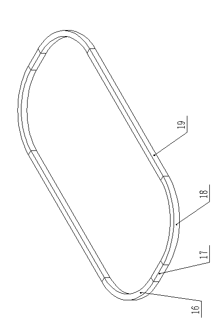
[0020] attached figure 1 As an embodiment of the present invention, combined with figure 1 And attached figure 2 This embodiment is specifically described, including a sliding rod guiding device, an annular guide rail sliding device, a belt transmission mechanism, a loading device and a base, and the sliding rod guiding device includes a sliding rod 1, a rotating shaft 2, a guide block 3 and a connecting plate 12, and the annular The guide rail sliding device includes an annular guide rail 7 and a slide block 8, the belt drive mechanism includes a left pulley 6, a right pulley 14 and a transmission belt 11, the loading device includes a carrier frame 9 and a loading plate 10, and the guide block 3 is provided with The cavity, the sliding rod 1 can slide back and forth in the cavity of the guide block 3, one side of the connecting plate 12 is fixedly connected with the sliding rod 1, the other side of the connecting plate 12 is glued and fixed with the transmission belt 11, a...


PUM


Abstract

Provided is a follow-up guiding type annual guiding rail feeding device. The follow-up guiding type annual guiding rail feeding device comprises a sliding rod 1, a rotating shaft 2, a guiding block 3, an annual guiding rail 7, a sliding block 8, a holding frame 9, a material carrying plate 10, and a driving belt 11. A cavity is formed in the guiding block 3, and the sliding rod 1 can slide in the cavity of the guiding block 3 from front to back. One side of a connecting plate 12 and the sliding rod 1 are fixedly connected into a whole, and the other side of the connecting plate 12 and the driving belt 11 are fixedly glued into a whole. The upper end surface of the rotating shaft 2 is connected with the lower bottom surface of the guiding block 3 in a rotating mode, and the lower end surface of the rotating shaft 2 is fixedly connected with the upper end surface of the sliding block 8. A left belt wheel 6 is connected with a right belt wheel 14 through the driving belt 11, and the driving belt 11 is sleeved on the two belt wheels. The holding frame 9 is fixedly connected with the sliding block 8, an arched groove is formed in the lower end portion of the holding frame 9, and the material carrying plate 10 is fixedly installed in the arched groove. The guiding rail 7 is fixedly connected with a boss of a pedestal 15. The sliding block 8 is embedded in the guiding rail 7 to form a sliding connection. Therefore, delivery of materials is more flexible and convenient.

Description

technical field [0001] The invention discloses a follow-up guide ring guide rail feeding device, which belongs to the field of automatic conveying equipment, and is specifically designed based on an ordinary curved sliding guide rail, and is driven by an existing double pulley combined transmission mechanism. Parts, equipped with a sliding rod guide device, a ring guide rail slide device, a belt drive mechanism, a loading device, a connecting plate and a base, a follow-up guide ring guide rail feeding device. Background technique [0002] In the field of automatic material conveying equipment, material conveying device is a very common and very important feeding tool, which is widely used in various material conveying occasions. With the changes of the times and the continuous development of science and technology, today's automated production lines are developing towards high speed, high precision and high reliability. In order to meet the requirements of modern production ...

Claims


Application Information

Patent Timeline
Patent Type & Authority Applications(China)
IPC IPC(8): B65G17/12B65G21/22
Inventor 宫文峰黄美发李雅萍陈磊磊
Owner GUILIN UNIV OF ELECTRONIC TECH
Why Eureka
Try Eureka