
Precisely positioned hydraulics

A hydraulic device and quantitative hydraulic technology, applied in the field of hydraulic devices, can solve the problems of high price of hydraulic components and achieve the effect of low procurement cost

Active Publication Date: 2016-08-03
KEDA INDUSTRIAL GROUP CO LTD
View PDF9 Cites 0 Cited by
  • Summary
  • Abstract
  • Description
  • Claims
  • Application Information

AI Technical Summary

Problems solved by technology

The traditional hydraulic control solution is to use the position servo hydraulic system, but its related hydraulic components are expensive, and the filtering accuracy of the hydraulic oil is strictly required, and a corresponding sophisticated and complex electronic control system is also required

Method used


Image

  • Precisely positioned hydraulics

Examples


Embodiment Construction

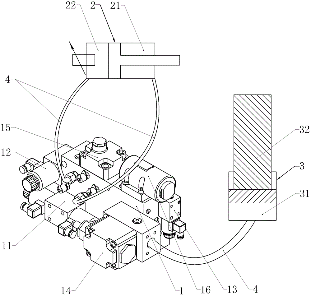
[0015] Such as figure 1 As shown, the precise positioning hydraulic device of the present invention includes an oil circuit block 1 , a stroke-adjustable quantitative hydraulic cylinder 2 and a positioning hydraulic cylinder 3 . The oil circuit block 1 is provided with a pressure oil circuit, a control oil circuit and an oil return circuit. The rod chamber and the rodless chamber of the stroke-adjustable quantitative hydraulic cylinder 2 are respectively connected to the oil circuit block 1 through the pipeline 4, and the oil circuit of the rod chamber 21 is connected with the control oil circuit of the oil circuit block 1, and the rodless The oil passage of the chamber 22 communicates with the oil return passage of the oil passage block 1 . The rodless chamber 31 of the positioning hydraulic cylinder 3 is connected to the oil circuit block 1 through the pipeline 4 and its oil circuit communicates with the control oil circuit and the return oil circuit of the oil circuit bloc...


PUM


Abstract

The invention discloses an accurate positioning hydraulic device comprising an oil path block, a quantitative hydraulic cylinder and a positioning hydraulic cylinder, wherein a pressure oil path, a control oil path and an oil return path are arranged in the oil path block; the rod chamber and rodless chamber of the quantitative hydraulic cylinder are connected to the oil path block through pipelines, respectively, and the oil path of the rod chamber is communicated with the control oil path of the oil path block while the oil path of the rodless chamber is communicated with the oil return path of the oil path block; the rodless chamber of the quantitative hydraulic cylinder is connected to the oil path block through a pipeline and the oil path thereof is communicated with the control oil path and the oil return path of the oil path block, respectively; a plurality of hydraulic elements are mounted on the oil path block; and the plurality of hydraulic elements include a first electromagnetic directional valve, a second electromagnetic directional valve and a third electromagnetic directional valve. The accurate positioning hydraulic device is capable of realizing accurate positioning of the positioning hydraulic cylinder only by using common electromagnetic directional valves; the related hydraulic elements and electronic control elements are standardized and universalized; the purchase cost is low; and common hydraulic filter precision is capable of meeting the requirements.

Description

technical field [0001] The invention belongs to the technical field of hydraulic control, and in particular relates to a hydraulic device mainly used for precisely positioning a pull rod of a vertical metal extrusion molding machine. Background technique [0002] In the existing vertical inner cavity metal extrusion molding machine (such as the vertical inner cavity metal extrusion molding machine of Keda Company), the tie rod needs to be accurately raised to a certain height before the tie rod can be entwined and fixed. The traditional hydraulic control solution is to use a position servo hydraulic system, but its related hydraulic components are expensive, have strict requirements on the filtration accuracy of hydraulic oil, and need to be equipped with a corresponding sophisticated and complex electronic control system. Contents of the invention [0003] The purpose of the present invention is to provide a hydraulic device with simple structure, low manufacturing cost a...

Claims


Application Information

Patent Timeline
Patent Type & Authority Patents(China)
IPC IPC(8): B21C31/00B21C26/00
Inventor 何浩波张昭政陈伟俊崔智敏
Owner KEDA INDUSTRIAL GROUP CO LTD
Learn More