Conical spring washer for mounting a stator in the housing of an electrical machine

A tensioning wheel and housing technology, applied in electrical components, electromechanical devices, electric components, etc., can solve problems such as the cost of vibration reduction solutions

Inactive Publication Date: 2013-06-12
ROBERT BOSCH GMBH
View PDF4 Cites 2 Cited by
  • Summary
  • Abstract
  • Description
  • Claims
  • Application Information

AI Technical Summary

Problems solved by technology

Conversely, alternative damping solutions have proven to be extremely costly

Method used


Image

  • Conical spring washer for mounting a stator in the housing of an electrical machine
  • Conical spring washer for mounting a stator in the housing of an electrical machine
  • Conical spring washer for mounting a stator in the housing of an electrical machine

Examples


Embodiment Construction

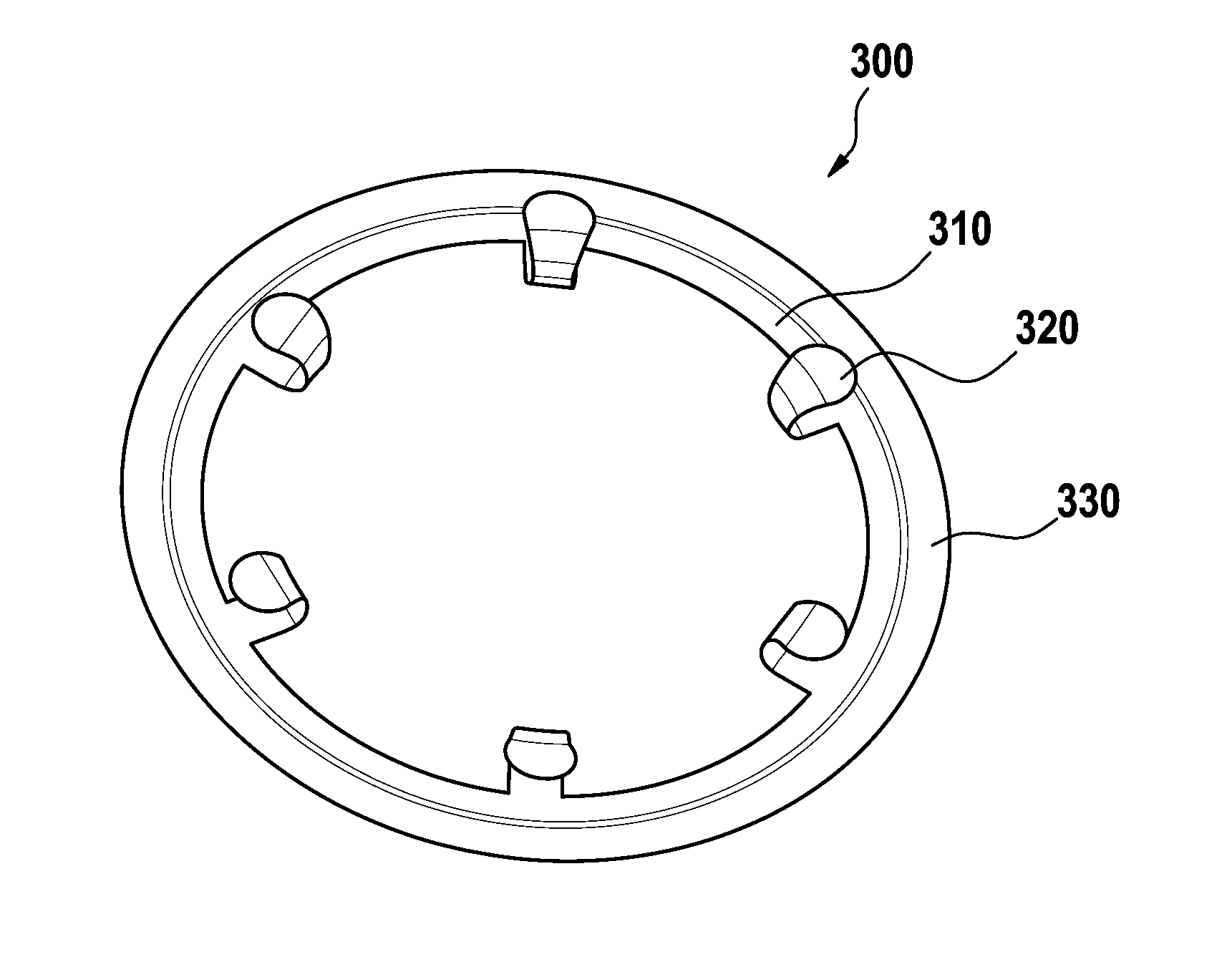
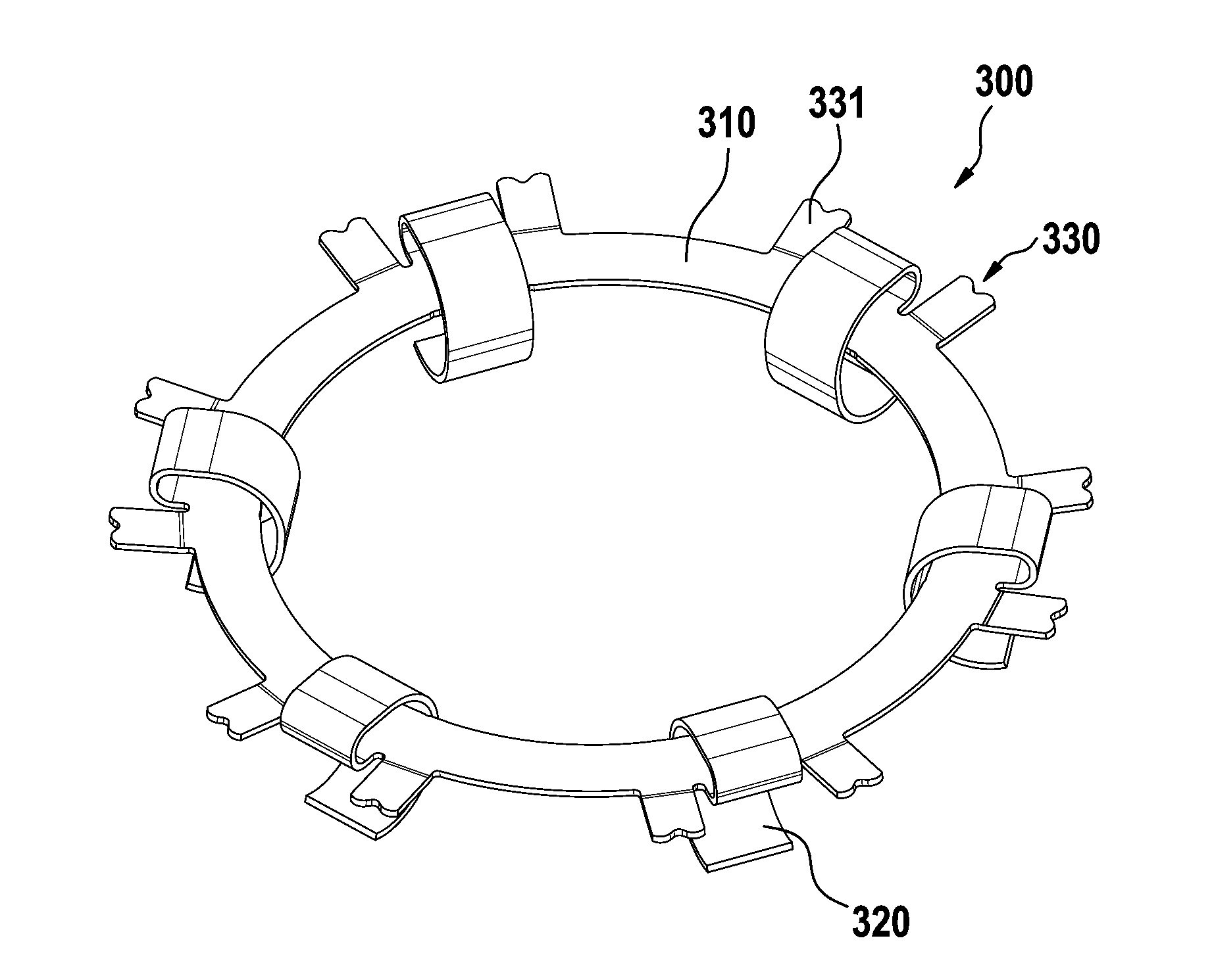
[0035] FIG. 1 is a perspective view of an electric machine 100 according to the invention. In the present example, the drive components, which are designed as hydraulic pumps, in particular the electric motors, which are designed as cooling circuit pumps, are shown here in a partially cutaway state. The motor 100 comprises a housing 110 made of a suitable material, such as plastic or metal, with an inner cavity 113 having a substantially circular cross-section, and an annular stator 200 disposed in the housing cavity and snapped into the annular The rotor 400 in the stator 200. In the hydraulic pump shown here, the rotor is arranged in an intermediate housing which separates the rotor chamber, which is flushed by the fluid from all sides, from the stator chamber. The intermediate housing is here formed by a cover element which closes the housing chamber on one side. According to the invention, stator 200 is fixed in its assembly position by means of tensioning pulley 300 . ...


PUM


Abstract

An electrical machine (100) comprises a housing (110), a stator (200) arranged in the housing and a conical spring washer (300), which holds the stator (200) in its installed position by means of a predetermined axial spring force (FA). In this case, the conical spring washer (300) comprises an annular base body (310), which is attached to a housing inner wall (110) by means of an attachment device (330), as well as a number of spring structures (320) which extend from the annular base body (310) in the direction of the stator (200) and support the stator (200) axially.

Description

technical field [0001] The invention relates to a tensioning pulley for fastening a stator in the housing of an electric machine, in particular a cooling circuit pump in a vehicle. Furthermore, the invention relates to an electric machine with such a tensioning pulley. Background technique [0002] Electric motors are used in various technical applications. Thus, for example an EC motor with a rotating rotor and a stationary stator arranged in the housing forms the electrical part of the cooling circuit pump. In order to reduce eddy currents, the stator formed from stamped, mutually insulated sheet metal is mechanically fixed by screwing, axially or radially tensioning, adhesively bonding, shrinking or pressing in, or by a combination of methods. connected to the housing. Many of these methods suffer from various drawbacks. Fastening the stator using screw connections is, for example, relatively space-consuming and cost-intensive. In addition, the preload of the screw c...

Claims


Application Information

Patent Timeline
Patent Type & Authority Applications(China)
IPC IPC(8): H02K1/18
CPCH02K1/185
Inventor J.蒂埃里J.施密德S.马福德C.海尔C.穆舍尔克瑙茨T.克尼希
Owner ROBERT BOSCH GMBH
Why Eureka
Try Eureka